Copyright © Cloud Software Group, Inc. All Rights Reserved


Chapter 18 High Availability Deployment Of Runtime Components : Introduction

Introduction
This chapter describes the deployment of run time components in a high availability setup. The runtime components are Core Engine, Cache Agents, Global Throttle Manager, Central Logger and Cache Cleanup Agents. You should deploy the runtime components in such a way that they are highly available in production systems to achieve maximum functionality of the gateway.
TIBCO API Exchange Gateway is deployed as a cluster of Core Engines that together act as a single logical gateway. The Core Engines in the cluster can run on a single server or in a distributed environment across multiple physical or virtual servers.
Typically for production deployment requirements, you require to add additional instances of Core Engines. The architecture of Core Engine has been designed so that when multiple Core Engine instances are deployed in a gateway cluster, the key management functions such as global throttle management, cache management, cache cleanup management and central logging are coordinated across all Core Engine instances.
However, as the levels of transactions increase, it is likely that there will be a corresponding increase in management activity. To avoid the possible impact of management activity upon the Core Engines of the TIBCO API Exchange Gateway, the management components (Global Throttle Manager, Cache CleanupAgent, and Central Logger) and the TIBCO Spotfire servers should be moved onto separate servers.
If multiple instances of the Core Engines are deployed in a cluster, you must start the Cache Agent instances explicitly once you start the Core Engines.
TIBCO Rendezvous is used for the communication between most of the runtime components of the gateway. The runtime components share a single set of configuration files.
Overview
This section gives an overview and configuration setup of the deployment of run time components with multiple instances for load balancing and high availability.
The administrators deploy two or more instances of the Core Engines in production to achieve high availability through load balancing. That is, a load balancer routes request messages to multiple Core Engine instances. The Core Engines together can handle more messages than just one Core Engine instance running. Also, such deployment makes the run time components highly available to process the requests with minimum or no down time. The Core Engine instances, thus, share the load of requests when large number of requests are received from the clients.
All the runtime components of the TIBCO API Exchange Gateway are deployed in the same cluster except the Central Logger component. The Central Logger instance must be running in a separate cluster.
Overview Of Deployment
Figure Overview of Runtime components For High Availability shows a high level overview of a deployment model of runtime components in a cluster for high availability setup.
Figure 33 Overview of Runtime components For High Availability
Operational Layer Components
This section briefly describes the information for load balancing setup of the Core Engines and Cache Agents.
Load Balancing Core Engines
All the instances of the Core Engine automatically behave in a fault tolerant manner. The load balancer distributes the load of requests within all active agents in the same group as per the configuration setup described in Configuring Load Balancer section. If any Core Engine instance fail, the load balancer distributes the load between the remaining active Core Engine instances in the group.
There is no discovery protocol between Apache server and the Core Engine. If one of the Core Engine instance goes down, the Apache server is not able to determine that this instance is not available and keeps sending the requests to the Core Engine which results in all those requests timing out. For this reason, it is recommended that you should not use a single Apache server to send request messages to multiple instances of the Core Engines.
For the Apache server and Core Engine configuration setup, you must consider following tips:
You must configure health monitor of the load balancer to call the gateway ping operation so that the load balancer can determine which instances of the Core Engines are up and running. See Configuring Load Balancer for configuration details. If any of the Apache server or the Core Engine instance goes down, the load balancer considers it as a failure to forward the request and routes the request to the second active instance of Apache server as configured in the load balancer group.
Cache Agents
TIBCO API Exchange Gateway supports in memory caching of the data. Fault tolerance of Cache Agents is handled transparently by the object management layer. For fault tolerance of cache data, the only configuration task is to define the number of backups you want to keep. Use of a backing store is not needed as the Cache Agents are only used to implement the association cache, which is automatically rebuilt after complete failure as new transactions are handled by the API Exchange Gateway.
Gateway Management Layer Components
The components of the Gateway Management Layer should be deployed once in a active-passive configuration setup. The Central Logger and the Global Throttle Manager need to have a single running instance at all times to ensure that the Core Engine operates without loss of functionality.
Therefore the Central Logger and Global Throttle Manager are deployed in fault tolerant configuration with one active engine (Central Logger instance or Global Throttle Manager instance) and one or more standby agents on a separate host servers. Such fault-tolerant engine setup can be configured in the cluster deployment descriptor (CDD) file by specifying the maximum number of one active agent for either of the agent classes and by creating multiple processing unit configurations for both the Global Throttle Manager and the Central Logger agent. Deployed standby agents maintain a passive Rete network. They do not listen to events from channels and they do not update working memory. The standby agents take over from the active instance in case it fails.
The Cache Cleanup agent of the Gateway Management Layer have no direct impact on the functionality of an operating API Exchange Gateway Engine instance. It is recommended that multiple versions of cache cleanup agents are deployed across host servers with one active instance running. If the running instance goes down, one of the other instances is started to regain full gateway functionality.
Example Deployment Model
Figure Deployment of Runtime Components In a Cluster illustrates the deployment of runtime components on the machines in a cluster environment for high availability.
Figure 34 Deployment of Runtime Components In a Cluster
It is recommended to have the runtime components deployed in a cluster as follows:
The figure Deployment of Runtime Components In a Cluster illustrates an example deployment model in which the components are deployed as follows:
All the run time components communicate using the Rendezvous channel. In the example deployment model as shown in Deployment of Runtime Components In a Cluster, its assumed that all the machines running various instances of runtime components are in the same subnet.
Configuration For High Availability Setup
This section describes the configuration of multiple processing units for load balancing and fault tolerance to achieve high availability and high throughput.
Configuration Files
The high availability configuration of run time components of the gateway can be setup in the asg_core.cdd and asg_cl.cdd files respectively. An agent class is an agent type, defined in the CDD file that deploys as an agent instance.
asg_core.cdd file defines the configuration for the following processing units:
default, asg-core, asg-caching-core - These processing units refers to the Core Engine. The configuration settings of core-class (Inference) agent class defines the runtime behaviour of default, asg-core, asg-caching-core agent processing units.
asg-cache - This processing unit refers to the Cache Agent. The configuration settings of cache-class (Cache) agent defines the runtime behaviour of asg-cache processing unit.
asg-cache-cleanup - This processing unit refers to the Cache Cleanup Agent. The configuration settings of cache-cleanup-esp (Query) and cache-cleanup-scheduler (Inference) agent classes define the runtime behaviour of asg-cache-cleanup processing unit.
asg-gtm - This processing unit refers to the Global Throttle Manager. The configuration settings of gtm-class (Inference) agent class defines the runtime behaviour of asg-gtm processing unit.
asg_cl.cdd file defines the configuration for the following processing unit:
asg_cl- This processing unit refers to the Central Logger. The configuration settings of BusinessEvents_Archive (Inference) agent class define the runtime behaviour of asg_cl processing unit.
To setup the deployment configuration of runtime components for high availability, do following steps:
Configuring Load Balancer
You must use a HTTP load balancer with API Exchange Gateway. For example, you can use the F5 load balancer. This section describes the configuration steps for F5 load balancer. If you use a different load balancer, you should refer to the documentation of the load balancer to complete the following tasks.
Create A Health Monitor For Core Engines
To create a monitor for the load balancer, follow these steps:
4.
Go to the Health Monitor tab of the navigation pane.
5.
Expand Monitors node under Local Traffic on left. Click the "+" to create a new monitor.
6.
7.
For General Properties section, input the values for the following fields:
a.
b.
Type: Select the type as HTTP from drop-down list
8.
For Configuration field, select BASIC from drop-down list.
9.
Input the values for the following fields under Configuration section as follows:
a.
b.
c.
d.
10.
Click the Finished button.
Create A Load Balancing Pool
This task is required to create a pool to load balance HTTP connections. You can use the configuration utility to create a load balancing pool.
To create a pool, do following steps:
1.
2.
On the left, under Local Traffic > Virtual Servers, select Pools node. Click the "+" to create a new pool.
3.
4.
In the upper-right corner of the screen, click Create. Verify that New Pool screen opens.
If the Create button is not available, make sure that you have permission to create a pool. Ask your administrator to grant Create Pool permissions to your user role.
5.
Type the name of the pool in the Name field. (for example, asg_http_pool.)
6.
For Configuration field, select BASIC from drop-down list.
7.
Under Configuration section, Go to Health Monitors sub-section.
a.
Select an existing health monitor from the Available field. For example, select asgping health monitor as created in Create A Health Monitor For Core Engines section.
b.
Click the Move button (<<) to move the monitor from the Available field to the Active field. For example move the asgping health monitor from the Available box to the Active box.
c.
Verify that the asgping health monitor appears under Active box.
8.
Under Resources setting, select an appropriate algorithm from the drop-down list for Load Balancing Method field. For example, you can select Round Robin.
9.
a.
Select the New Address option.
b.
c.
In the Service Port field, enter the service port of HTTP module on that machine. (for example, type 80, or select HTTP).
d.
Click Add.
e.
10.
Click Finished button.
Create a Virtual Server
This task is required to create a virtual server. The virtual server processes the HTTP traffic and send it to the pool.
You can use the Configuration utility to create the virtual server. To create a virtual server, do following:
1.
2.
Expand Local Traffic node. Click Virtual Servers.
3.
4.
If the Create button is not available, make sure that you have permission to create a virtual server. Ask your administrator to grant permissions to create virtual server for your role.
5.
In the Name box, type a name for the virtual server (example vs_http).
6.
In the Destination box, verify that the type of virtual server is Host.
7.
In the Address box, type an IP address for the virtual server.
8.
In the Service Port box, type 80, or select HTTP from the list.
9.
In the Configuration area of the screen, locate the HTTP Profile setting and select HTTP. This assigns the default HTTP profile to the virtual server.
10.
In the Resources section of the screen, locate the Default Pool setting and select the name of the HTTP pool created in the Create A Load Balancing Pool section.
11.
From the Default Persistence profile setting, select profile_none as the profile.
12.
Configuring Apache Modules for Core Engines
You must configure the Rendezvous subject for each Core Engine instance and Apache module so that the requests from the Apache server are forwarded to the correct instance of the Core Engine.
Set the Rendezvous Connection Parameters For Apache Module
For each machine running the Apache server, set the Rendezvous parameters for Apache module as follows:
1.
Browse to ASG_HOME/modules/http_server/apache directory.
2.
Edit the mod_ASG.conf file.
3.
Set the AsgSubject parameter, which must be defined unique for each machine. For example, this can be set be follows:
   AsgSubject ASG_CoreEngine1_Subject1
4.
5.
Set the Rendezvous Connection Parameters for Core Engine
For each machine running the Core Engine instance, set the properties for Rendezvous connection as follows:
1.
Navigate to the ASG_CONFIG_HOME directory.
2.
Edit asg.properties file.
3.
Set the tibco.clientVar.ASG/modRV/north_request property, which must be defined unique for each machine. For example, this can be set as follows:
tibco.clientVar.ASG/modRV/north_request=ASG_CoreEngine1_Subject1
The value of tibco.clientVar.ASG/modRV/north_request property must match the AsgSubject defined in the mod_ASG.conf file for that machine.
4.
5.
Cluster Configuration For Runtime Components
This section explains the configuration to setup the cluster properties. A cluster defines the machines running the Core Engines, Global Throttle Manager, Cache Agent and Cache Cleanup Agents. You must define all run time components in the same cluster except the Central Logger component. The Central Logger instance must be deployed in a separate cluster.
Configuration Files
The cluster properties are defined in the asg_core.cdd and asg_cl.cdd files.
To define the machines in a cluster, you must set the discover URL for the cluster.
Discover URL
The discover URL specifies how the Core Engine (node) listens for discovery requests from nodes attempting to join the cluster. When a cluster starts up, and also when new members join a cluster, a discovery process enables the members to discover each other. The discover URL specifies how an Core Engine (node) listens for discovery requests from nodes attempting to join the cluster.
The discovery URL for well-known address configuration uses the following format:
   tcp://machine1_ipaddress:port;machine2_ipaddress:port;machine3_ipaddress:port/
where machine1, machine2, machine3 belong to same cluster.
Configure Discover URL
The discover URL for a cluster is defined in the Properties section of the Cluster tab in the ASG_HOME/bin/asg_core.cdd and ASG_HOME/bin/asg_cl.cdd files. The discover URL is defined on each machine where the runtime component runs.
Edit asg_core.cdd File To Set Discover URL (using text editor)
To edit the discover URL and listen URL, follow these steps:
1.
Open the ASG_HOME/bin/asg_core.cdd file for editing.
2.
Edit the following properties and set the value to the actual IP addresses of the machines in a cluster, and an unused port.
For example, if the Core Engine instance 1 is running on Machine C, Core Engine instance 2 is running on Machine D, Cache Agent instance 1 is running on Machine C, Cache Agent instance 2 is running on Machine D, Cache Cleanup Agent instance 1 is running on Machine C, cleanup agent instance 2 is running on Machine D, Global Throttle Manager instance 1 is running on Machine E, Global Throttle Manager instance 2 is running on Machine F, then set the URL as follows, where port1 is an unused port:
   <property-group comment="" name="cluster">
   <property name="be.engine.cluster.as.discover.url"
   value="tcp://Machine C_IP_address:port1;Machine D_IP_address:port1;
                        Machine E_IP_address:port1; Machine F_IP_address:port1/"/>
   </property-group>
3.
Save the changes to asg_core.cdd file.
Edit asg_cl.cdd File To Set Discover URL (using text editor)
To set the discover URL for a cluster containing the machines where the Central Logger instances are running, you must edit the ASG_HOME/bin/asg_cl.cdd file on each machine as follows:
1.
Open the ASG_HOME/bin/asg_cl.cdd file for editing.
2.
Edit the following properties and set the value to the actual IP addresses of the machines in a cluster, and an unused port.
For example, if the Central Logger instance 1 is running on Machine E, Central Logger instance 2 is running on Machine F, then set the URL as follows:
   <property-group comment="" name="cluster">
   <property name="be.engine.cluster.as.discover.url"
   value="tcp://Machine E_IP_address:port2;Machine F_IP_address:port2/"/>
   </property-group>
3.
Save the changes to the asg_cl.cdd file.
To edit the asg_core.cdd and asg_cl.cdd files using the Studio to set the discover URL, See Editing CDD File using Studio.
Configuring Fault Tolerance Parameters
For the Core Engines, you should run the multiple instances across the servers in a load balanced setup. The configuration for load balanced setup is defined in the asg_core.cdd file. See Configuring Core Engines.
For the Cache Cleanup Agent, Global Throttle Manager and Central Logger components, the instances must be deployed as one active engine and one or more stand by agents that run on a separate server. See Configuring Cache Cleanup Agent, Configuring Global Throttle Manager and Configuring Central Logger.
The maximum number of active instances are configured as an agent class configuration parameter. An agent class is an agent type, defined in the CDD file that deploys as an agent instance.
The following parameters define the fault tolerant configuration of run time components:
This section explains the steps to set the maximum number of active instances and priority required for the high availability of runtime components.
Configuring Core Engines
You must run the multiple Core Engine instances as Active to achieve load balancing. Out of the box, API Exchange Gateway provides the configuration parameters for load balancing, which are set in the ASG_HOME/bin/asg_core.cdd file. You can run multiple instances of the Core Engine using the configuration parameters set in the ASG_HOME/bin/asg_core.cdd file. By default, you can run unlimited number of instances.
For the Core Engine Active Active instances, Max Active and Priority parameters are not applicable.
Example Settings for Core Engine Instance
Just as a reference, this section shows the sample settings for the Core Engines in the ASG_HOME/bin/asg_core.cdd (XML file). By default, no changes are required to run multiple instances of the Core Engine.

 
<inference-agent-class id="core-class">
   <load>
     <max-active/>
   </load>

 
Configuring Cache Agent
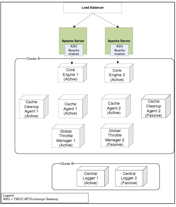
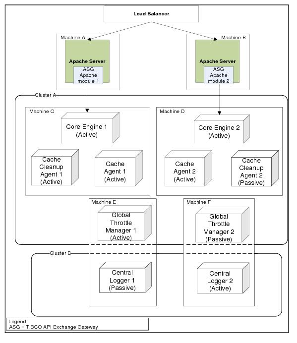
The Cache Agents behave according to the cache object management configuration set in the Cluster tab of the CDD file. Refer to CDD Cluster Tab Cache OM Settings table for the object management configuration parameters.
Out of the box using the default configuration in the asg_core.cdd file, you can run more than one instance of Cache Agent.
Example Settings For Cache Agent Instance
This section shows the sample settings for Cache Agents in the ASG_HOME/bin/asg_core.cdd (XML) file. You can use the sample settings as a reference by editing the ASG_HOME/bin/asg_core.cdd (XML) file in a text editor.

 
<object-management>
       <cache-agent-quorum>1</cache-agent-quorum>
       <backup-copies>1</backup-copies>
   </cache-manager>
</object-management>

 
Configuring Cache Cleanup Agent
To run the Cache Cleanup Agent instances in a fault tolerant mode, you must set the Max Active property. Optionally, you can configure Agent Priority parameter. The Max Active and Priority parameters are defined in the asg_core.cdd file. See Fault Tolerant Configuration Parameters for description of parameters.
To set the number of the active instances and priority for the Cache Cleanup Agent instances, follow these steps:
1.
Navigate to the ASG_HOME/bin directory.
2.
Edit the asg_core.cdd file. You can edit the file either using a text editor or using the Studio. See Editing Cluster Deployment Descriptor (CDD) File.
3.
If you use the Studio, set Max Active property for cache cleanup agents as follows:
a.
Select Agent Classes tab.
b.
Select the cache-cleanup-scheduler (Inference) agent.
c.
      Max Active 1
d.
e.
      Max Active 1
4.
5.
Optionally, you can set the Priority for the processing units as follows using the Studio:
a.
Select Processing Units tab.
b.
Select the asg-cache-cleanup node.
c.
On the right side, in the Agents section, set the priority for following agents:
d.
Double click the Priority column to set a value, if required.
6.
Example Setting For Cache Cleanup Agent Instance
This section shows the sample settings for cache cleanup agents in the ASG_HOME/bin/asg_core.cdd (XML) file.
You can use the sample settings as a reference to set the values by editing the ASG_HOME/bin/asg_core.cdd (XML) file in a text editor:

 
   <query-agent-class id="cache-cleanup-esp">
     <load>
       <max-active>1</max-active>
     </load>
   </query-agent-class>
 
   <inference-agent-class id="cache-cleanup-scheduler">
     <load>
       <max-active>1</max-active>
     </load>
   </inference-agent-class>
 
   <processing-unit id="asg-cache-cleanup">
     <agents>
       <agent>
         <ref>cache-cleanup-esp</ref>
          <key/>
           <priority/>
       </agent>
       <agent>
         <ref>cache-cleanup-scheduler</ref>
          <key/>
           <priority/>
       </agent>
     </agents>

 
Configuring Global Throttle Manager
To run the Global Throttle Manager instances in a fault tolerant mode, you must set the Max Active property. Optionally, you can configure Agent Priority parameter. The Max Active and Priority parameters are defined in the asg_core.cdd file. See Fault Tolerant Configuration Parameters for description of parameters.
To set the number of the active instances and priority for the Global Throttle Manager instances, follow these steps:
1.
Navigate to the ASG_HOME/bin directory.
2.
Edit the asg_core.cdd file. You can edit the file either using a text editor or using the Studio. See Editing Cluster Deployment Descriptor (CDD) File.
3.
Set the Max Active property as follows for the Agent Classes > gtm-class (Inference) agent. See Set Max Active using the Studio.
      Max Active 1
4.
5.
Optionally, you can set the priority for the asg-gtm processing unit using the Studio as follows. See Set Priority.
a.
Go to Processing Units tab.
b.
Select the asg-gtm node.
c.
Go to Agents section, and select the row with gtm-class agent.
d.
Set a value for Priority. For example, you can set this value to 2.
6.
Example Setting For Global Throttle Manager Instance
This section lists the sample settings for the Global Throttle Manager instance in the ASG_HOME/bin/asg_core.cdd (XML) file.
Use the sample settings as a reference to set the values by editing the ASG_HOME/bin/asg_core.cdd (XML) file in a text editor:

 
   <inference-agent-class id="gtm-class">
      <load>
      <max-active>1</max-active>
      </load>
   </inference-agent-class>
 
   <processing-unit id="asg-gtm">
    <agents>
     <agent>
     <ref>gtm-class</ref>
        <key/>
        <priority>2</priority>
     </agent>
    </agents>

 
Configuring Central Logger
To run the Central Logger instances in a fault tolerant mode, you must set the Max Active property. Optionally, you can configure Agent Priority parameter. The Max Active and Priority parameters are defined in the ASG_HOME/bin/asg_cl.cdd file. See Fault Tolerant Configuration Parameters for description of parameters.
To set the number of the active instances and priority for the Central Logger instances, follow these steps:
1.
Navigate to the ASG_HOME/bin directory.
2.
Edit the asg_cl.cdd file. You can edit the file either using a text editor or using the Studio. See Editing Cluster Deployment Descriptor (CDD) File. If you use the Studio, follow these steps:
a.
Open the ASG_HOME/bin/asg_cl.cdd file using the steps described in Editing CDD File using Studio.
b.
Select Agent Classes tab.
c.
Select the BusinessEvents_Archive (Inference) node.
d.
      Max Active 1
e.
3.
Optionally, you can set the priority for the asg-cl processing unit using the Studio as follows. See Set Priority.
a.
Go to Processing Units tab.
b.
Select the asg_cl node.
c.
Go to Agents section, and select the row with BusinessEvents_Archive agent.
d.
Double click the Priority column to set a value. For example, you can set this value to 5.
e.
Example Settings For Central Logger Instance
This section lists the sample settings for the Central Logger instance in the ASG_HOME/bin/asg_cl.cdd (XML) file.
You can use these sample settings as a reference to set the values for max-active and priority by editing the ASG_HOME/bin/asg_cl.cdd (XML) file in a text editor:

 
   <inference-agent-class id="BusinessEvents_Archive">
     .....
     .....
      <load>
       <max-active>1</max-active>
      </load>
 
   <processing-unit id="asg-cl">
    <agents>
     <agent>
      <ref>BusinessEvents_Archive</ref>
        <key/>
        <priority>5</priority>
     </agent>
    </agents>

 
4.
Configure Rendezvous Session Connection Parameters
You must configure the Rendezvous session connection parameters for the Core Engine instances to communicate with the Global Throttle Manager instances and the Central Logger instances, in case, the Rendezvous daemon runs with the non-default session parameter settings on the machines where these components are running.
The parameters are defined in the ASG_CONFIG_HOME/asg.properties file and ASG_CONFIG_HOME/asg_cl.properties file. See following sections for the list of connection parameters:
The instances of the runtime components illustrated in the deployment Deployment of Runtime Components In a Cluster assumes the following points:

Copyright © Cloud Software Group, Inc. All Rights Reserved