Using the Console
The iWay TPM console is responsible for managing trading partner data. This section describes how to navigate and use the console to work with partners and all of the available facilities.
Access the Console
To access the console:
- Procedure
- Enter the following URL in your web browser, where 8092 is the port number that you specify for the iWay Trading Partner Manager server during the installation.
http://localhost:8092
The login screen opens, as shown in the following image.
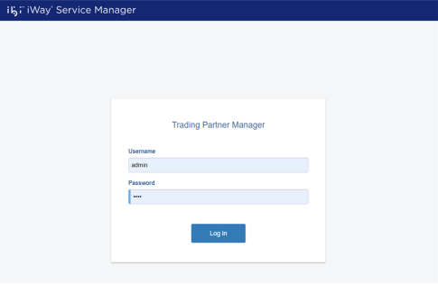
- Enter admin as the user name (default) and iway as a password.
- Click Sign in.
The console opens, as shown in the following image.
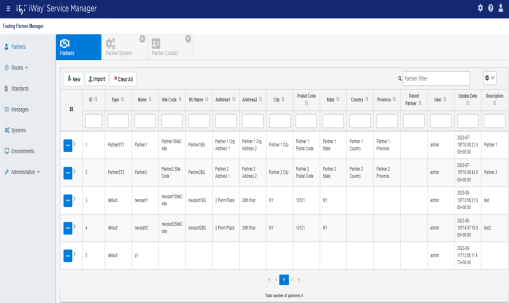
The various iWay TPM facilities can be accessed by clicking the tabs at the top of the pane.
The following sections describe the facilities in more detail:
-
For more information about using the Partners facility, see Partners.
-
For more information about using the Routes facility, see Routes.
-
For more information about using the Standards facility, see Standards.
-
For more information about using the Messages facility, see Messages.
-
For more information about using the Systems facility, see Systems.
-
For more information about using the Environments facility, see Environments.
-
For more information about using the Administration facility, see Administration.
-
Navigating the Console and Common Usability Features
There is an array of usability features that are shared by all the facilities within the console. This section covers the basic usability features available. Note that the availability of some of the features described in this section are dependent on the user privileges.
User Profile (Sign Out)
To view your user profile or to sign out of the console, click the User Profile icon, which is located in the upper-right corner of the console, as shown in the following image.

A user profile dialog expands, which also includes a Sign Out button, as shown in the following image.
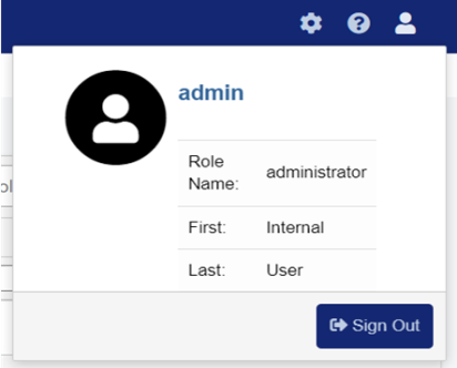
To close this dialog, click anywhere outside of this area. If you need to sign out, click Sign Out, and you are returned to the iWay TPM login screen.
Version and Build Information
To view your iWay TPM version and build information, which may be requested if you contact Customer Support, click the About TPM icon, which is located in the upper-right corner of the console, as shown in the following image.

The About TPM Console dialog opens, as shown in the following image.
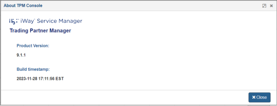
Click Close to return to the console.
Console REST API
iWay TPM includes a wide selection of REST API calls that can be accessed through a Swagger-based UI. To access the REST API, click the TPM Console REST API icon, which is located in the upper-right corner of the console, as shown in the following image.

The TPM Console REST API opens in a new browser tab, as shown in the following image.
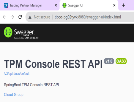
Close this browser tab to return to the console.
For more information on the iWay TPM REST API, see ibi iWay Trading Partner Manager REST API Reference.
Showing and Hiding the Left Navigation Pane
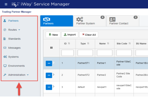
The left navigation pane displays by default when you log in to the console, as shown in the following image.
You can quickly toggle (show or hide) this navigation pane as required. For example, you may want to view additional columns in the Partners area. To hide this navigation pane, click the Navigation Toggle icon, as shown in the following image.
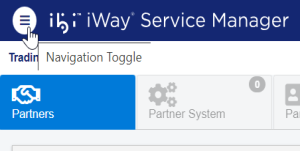
The navigation pane is now hidden, as shown in the following image.
To restore the navigation pane, click the Navigation Toggle icon again.
Pagination Tool
Located at the bottom of the main pane for each category, the pagination tool allows you to quickly navigate through the pages of all defined components (for example, partners, routes, systems, and so on).
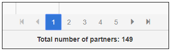
If a large number of components are defined, you can go to the next page by clicking the right arrow button. To navigate to the last page of the set, click the End button. By default, the first 10 objects of the set are displayed based on the latest edited information.
Working With Table Columns
This section describes how to work with table columns in the console.
Showing and Hiding Columns
You can toggle (show/hide) specific columns on each defined component page (for example, partners, routes, systems, and so on). A drop-down menu is available on the right side of each page, as shown in the following image.
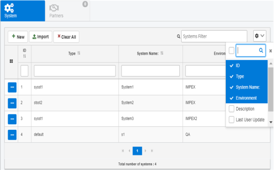
Click the drop-down menu and select or deselect the column(s) for display in the table.
Resizing Columns
To resize a column in the table, hover your cursor between any two columns. Your cursor changes and displays a resize option. Drag to the left or to the right to resize the column as required and release the cursor.
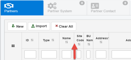
The column is resized, as shown in the following image.
Moving Columns
You can also move (reorder) any columns in the table as required. Hover your cursor on the header of the column you want to move.
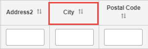
Click and drag the column to its new location in the table. The following image shows the City column being moved to the right of the Postal Code column.
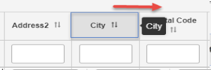
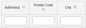
Release the cursor to drop the column in its new position.
Sorting
You can quickly sort column values (lowest to highest, highest to lowest, A to Z, or Z to A) by clicking the sort arrow in the column header, as shown in the following image.
The column values are refreshed accordingly.
You can also sort by a specific term or keyword. Begin typing a value in the column header field, which also auto completes your entry based on available data, as shown in the following image.
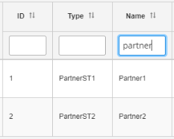
The column values are refreshed based on your entry.
Filtering
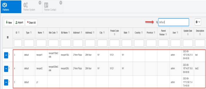
To filter values on a page, simply type a value in the filter field, located in the upper-right as shown in the following image.
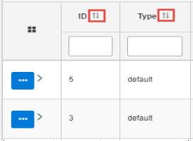
You can also filter on a specific column by entering a value in the filter field located below the column name. For example, you can enter a value for Type.
The table on the page is refreshed based on your entry.
To clear the filtered results and reset the table, click Clear All, as shown in the following image.
![]()
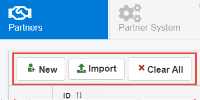
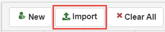
Buttons
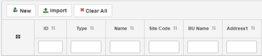
Located at the top pane for each category, buttons enable the user to perform common actions. The following image shows the buttons that are available on the Partners page
The following table lists and describes several key buttons.
|
Button |
Description |
|---|---|
|
|
Creates a new entry for a particular asset. For example, on the Partners page, this button is used to add a new partner. |
|
|
This button allows you to import a previously-exported entity from a JSON (.json) file. |
|
|
Clears any filters or selections on the column level and page level. |

Import UI
The Import functionality enables you to import a previously-exported entity as a JSON document. This functionality is available for every component of Trading Partner Manager, eg. Partners, Partner System, Partner System Messages, Standards, Advanced Routes, etc.
- Procedure
- To import a UI component from previously-exported JSON document, click Import, as shown in the following image.
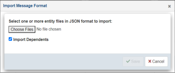
- The Import dialog opens, as shown in the following image.
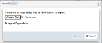
- Click Choose Files to select previously-exported JSON documents. Select the Import Dependents check box to import dependents if they are present in the JSON document.
-
Click Save to import the entity data and refresh the table.
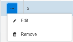
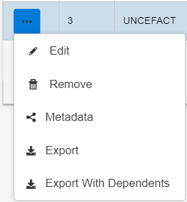
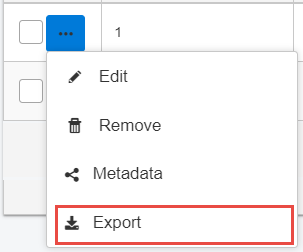
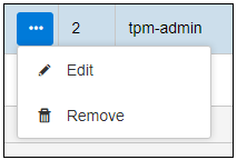
Menu Options
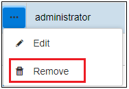
For a selected entity, click the ellipsis menu to view the menu options. The options may vary depending on the selected entity. The following menu options are commonly available:
|
Menu Item |
Description |
|---|---|
|
Edit |
Opens a dialog to edit the fields in selected row. |
|
Remove |
Deletes the entry. |
| Metadata | Opens a dialog that lists the metadata configured in Metadata Configuration. |
|
Export |
Downloads the selected entity's data as a JSON document. |
|
Export With Dependents |
Downloads the entity data along with its dependent entities. Shows a dialog with the list of dependents. |
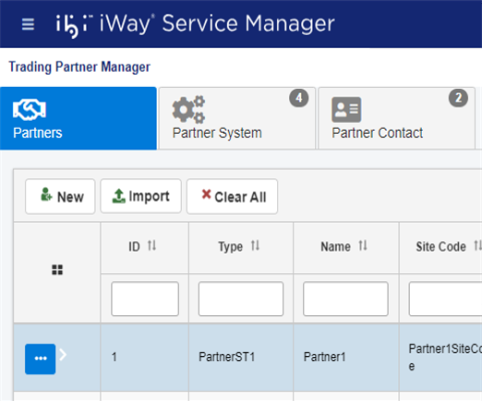
Partners
Partner is defined as either a physical or logical end-point. A partner most commonly represents an organization which sends and/or receives messages using a configured application. Partner information constitutes a set of attributes about partner characteristics as a unit, and defines the type of messages that can be processed by the partner and on various systems.
The following image represents a relationship between Partner and System which is formed through a Partner System definition.
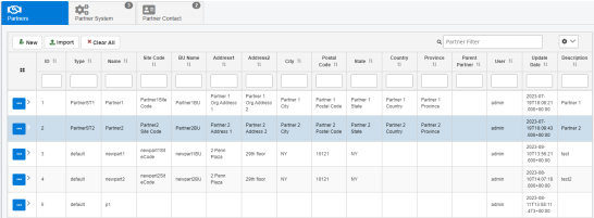
The Partner page is used to manage partner information, partner contacts, and partner systems. The initial view of the partner displays the Partner Information screen where the user is able to open additional sections by clicking on the menu list.
You can select a specific partner from the table and click the options menu to edit it. The menu also provides the options to Copy, Remove, edit Metadata, Export, and Export With Dependencies.
The following partner information tabs are available:
- Partners. This tab provides general partner information such as name, address, and so on.
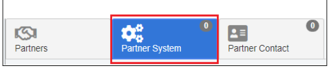
- Partner System. This tab shows the systems associated with a partner for processing messages.
- Partner Contact. This tab provides partner contact information which can consist of multiple contacts within an organization.
Partner Information
This section provides an example of the partner information pane that displays when a partner is selected.
The following table lists and describes the properties in the Partners tab.
|
Property |
Description |
|---|---|
|
ID |
ID number that is associated with the partner. |
| Type | The domain subtype defined in the Administration>Metadata>Metadata Configuration. |
| Name | The required unique partner name to identify a specific partner. |
| Site Code | Optional site code to be assigned as a partner attribute. |
| BU Name | Optional business unit name to be assigned as a partner attribute. |
|
Address 1 |
Required first line of the partner address. |
|
Address 2 |
Optional second line of the partner address. |
| City | Required name of the city or town for the partner address. |
|
Postal Code |
Required ZIP or Postal code for the partner address. |
|
State |
Optional state (if applicable). |
|
Country |
Required country for the partner address. |
|
Province |
Optional Province (if applicable). |
|
Parent Partner |
A selection of existing partners which can be assigned as a parent partner. This enables the child partner to store local unique attributes, while the parent partner stores shared attributes for multiple child partners. |
| User | Indicates the user who last updated the information. |
|
Update Date |
Indicates the last update date and time. |
|
Description |
Optional, but recommended, description of the function of the partner. |
Partner System
The Partner System tab is designed to store systems and system messages which correspond to a given partner. Note that the system can be either a logical or real resource (such as channel, target, and so on). This view enables the management of systems, which can process assigned messages for a given partner. For example, if a partner has two systems associated with it, where the first system can process messages of type A and the second system can process messages of type B, then at runtime it can be routed to a proper system for processing (for example, sending to a proper internal queue, channel, or adapter target) simply by examining a message and determining its type.
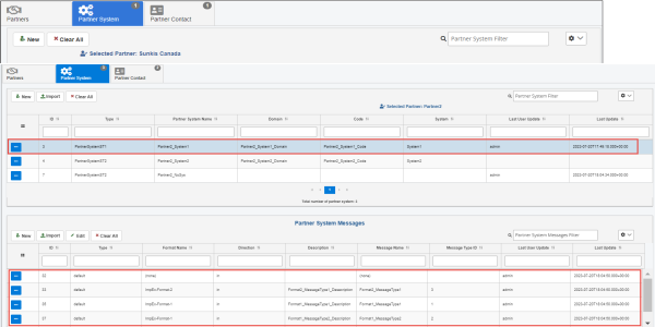
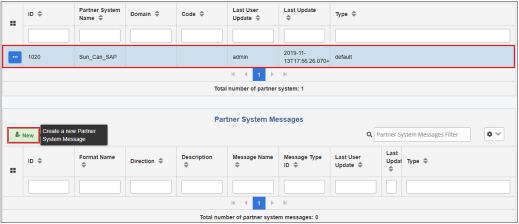
The following image shows a single partner system with three types of messages which can be processed on this system.
To edit the partner system properties, select a partner system from the table, and then click Edit from the options menu, as shown in the following image.
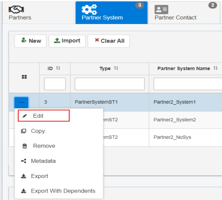
The Edit Partner System dialog opens, as shown in the following image.
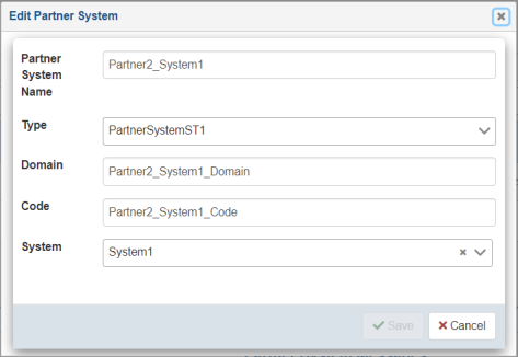
The following table lists and describes the properties you can modify for a partner system.
|
Property |
Description |
|---|---|
|
ID |
ID number that is associated with the partner system. |
| Type | Specify a predefined type (optional). |
| Partner System Name | Required and unique partner system name that identifies the partner and system relationship. |
|
Domain |
Optional Domain (if applicable). |
|
Code |
Optional System Code (if applicable). |
|
System |
Optional selection of existing system as defined under the System pane. If selected, the system must be predefined before a partner system relationship can be established. |
| Last User Update | Indicates the user who last updated the information. |
| Last Update | Indicates the last update date and time. |
Click Save after you have finished editing the partner system information.
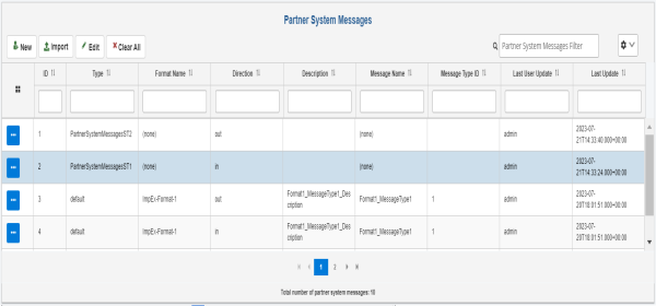
Partner System Messages
The Partner System Messages pane defines a set of messages that can be processed by a given partner system. It also establishes the direction for message processing such as the in and out direction. The values in the Message Type ID or Format Name columns can be defined prior to the partner system messages configuration and are selectable from the available messages, or the value can be none.
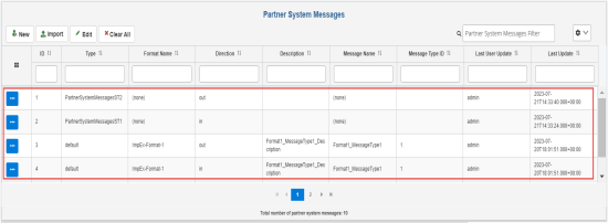
The following image shows two messages that can be processed as input and two messages that can be processed as output for a given partner system. A complete relationship between partner, system, and message is known as a business channel.
Partner Contact
The Partner Contacts tab is designed to store contact information for a partner. Some uses might include contact information to whom notifications for unprocessed or erroneous transactions are sent. The following image shows a sample partner contact.
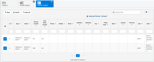
The following table lists and describes the properties in the Partner Contact tab.
|
Property |
Description |
|---|---|
|
ID |
ID number that is associated with the partner contact. |
| Type | The domain subtype defined in the Administration>Metadata>Metadata Configuration. |
|
Name |
Required, unique contact name. |
|
Primary Contact |
Select either true or false to indicate if this is the main contact. |
|
Auto Notify Contact |
Used in message processing logic, select either true or false to identify if the failed messages should or should not always be sent to this contact (recommended setting is false). |
|
Phone |
Phone number of the contact. |
|
Mobile |
Mobile phone number of the contact. |
|
|
Email address of the contact, which must be of proper email format. |
|
Address 1 |
First line of the address of the contact. |
|
Address 2 |
Second line of the address of the contact. |
|
City |
City or town for the address. |
|
Postal Code |
ZIP or Postal code for the address. |
|
State |
State for the address (if applicable). |
|
Country |
Country for the address. |
|
Province |
Province for the address (if applicable). |
|
User |
Indicates the user who last updated the information. |
| Date | Indicates the last update date and time. |
Add a Partner
A new Partner requires a definition of partner information, system, and Partner Systems which ties the given system to a given partner. The Partner System is critical, since a single system can be shared by multiple partners for message processing.
The following list represents general components which have to be created for a full Partner profile.
- Partner. This component contains general partner information as defined on the Partner Information screen.
- Partner System. This component establishes a defined Partner System and Messages which can be processed by a given partner on a given system. This is defined on the Partner screen under Partner Systems.
- System. System definition available for multiple partners to share. This is defined on the Systems screen. For more information, see Systems.
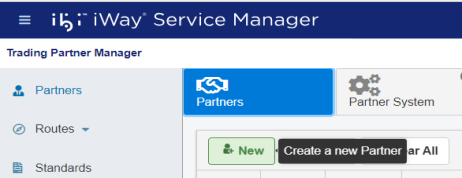
To add a trading partner using the console:
- Procedure
- Select the Partners tab in the console,
and click New to add a new partner.
The New Partner dialog opens, as shown in the following image.
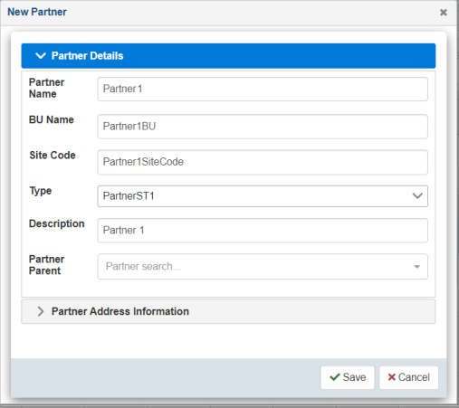
Two subtabs are available (Partner Details and Partner Address Information).
- Enter the information for the partner you are
creating.
The following table lists and describes the properties in the New Partner dialog.
Property
Description
Partner Details
Partner Name
Unique name given for the partner.
BU Name
Name of the Business Unit.
Site Code
Site code of the partner.
Type
Specify a predefined type (optional).
Description
Partner function description.
Partner Parent
Select the partner parent if applicable. Partner parents can carry the main information, and child partners can have specific information. For example, the Sunkis partner parent has main contacts, while the Sunkis Canada child partner has regional contacts.
Partner Address Information
Organization Address 1
First line of the address.
Organization Address 2
Second line of the address.
City
Name of the city.
Postal Code
Postal code of the city.
State
State (if applicable).
Province
Province (if applicable).
Country
Country of the partner.
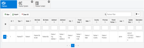
- Click Save when
you are finished.
The new trading partner is added, as shown in the following image.
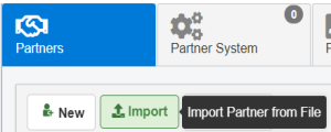
-
You can also import a Partner from previously-exported Partner JSON documents. Click Import, as shown in the following image.
-
The Import Partner dialog opens, as shown in the following image.
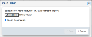
-
Click Choose File to select previously-exported Partner JSON documents. Select the Import Dependents checkbox to import dependents if they are present in the JSON document.
-
Click Save to import the Partner data and refresh the table.
Associate a Partner System with a Partner
- Procedure
- To associate a partner system with the
partner you just created, select the trading partner in the Partners table and then click Partner System from the menu, as shown in the following image.
 Note: A trading partner system must already be available in the Systems section of the console. For more information, see Systems.
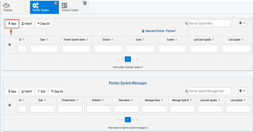
 - Click New to create a new Partner System, as shown in the following image.
The New Partner System dialog opens, as shown in the following image.
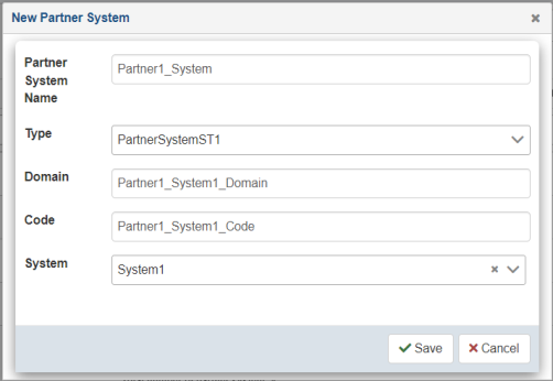
Partner system creation enables the linkage of partner and specific system(s) which can process corresponding messages. This is a logical link which is later used by an application at runtime.
- Enter the information for the trading partner system
you are creating. Optionally, select an existing system from the System drop-down
list.
The System drop-down list is populated with available systems that have been created using the Systems facility. As a result, you must define a system before it can be associated with a trading partner. For more information, see Systems.
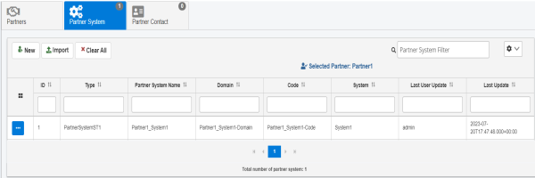
- Click Save when you
are finished.
The new trading partner system is added, as shown in the following image.
Associate a Set of Messages with a Partner System
- Procedure
- To associate a set of messages with a trading partner
system, select the partner system from the table and click New in
the Partner System Messages area, as shown in the following image.
The New Partner System Message dialog opens, as shown in the following image.
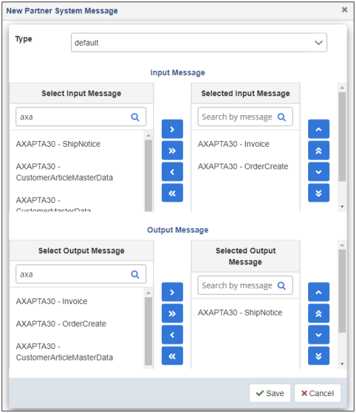
This dialog enables you to select the input and output message types to be processed by the selected trading partner system.
- From the Select Input Message and Select Output Message lists on the left, select the required system messages to be added. Use the available buttons to add them to the Selected Input Message and Selected Output Message lists on the right side.
- Click Save when
you are finished.
You are returned to the Partner System Messages pane, which now lists the message(s) you selected for the trading partner system, as shown in the following image.
 Note: The same message can be associated with multiple systems and partners, but based on its unique metadata attributes, it can be processed differently at runtime.
Routes
A business route is a combination of an inbound business channel and an outbound business channel, where each channel is a combination of a system that is sending or receiving messages of a partner. For a complete relationship, the user must define a Partner, the Partner System, and the Message Type prior to defining a route. The route always sends messages in one direction. To establish a bi-directional relationship, you must create two routes. Routes enable the application to dynamically retrieve the stored relationship between partners and identify the routing mechanism and direction to be used.
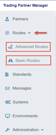
The Routes menu in iWay TPM has two types of routes, Advanced Routes and Basic Routes. You can view the list of existing routes or create a new route using this menu.
Create an Advanced Trading Partner Route
To create an advanced trading partner route using the console:
- Procedure
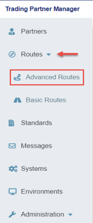
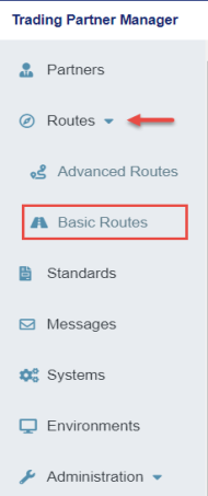
- Expand Routes from the left navigation pane in the console and click Advanced Routes, as
shown in the following image.
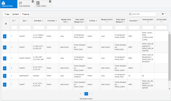
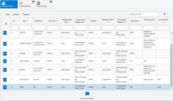
The Advanced Routes page opens, as shown in the following image.
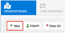
- Click New to add a new route, as shown in the following image.
The New Advanced Route dialog opens, as shown in the following image.
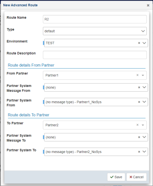
- Enter the information for the trading partner route you are
creating, as required.
The following table lists and describes the properties of the New Route dialog. An asterisk (*) character indicates a required property.
Property
Description
Route Name
Unique name for the route.
Type
Specify a predefined type (optional).
Environment
Environment in which this route exists.
Route Description
Optional description for the route.
Route details From Partner
From Partner
Initializing partner from which the message is being received.
Partner System Message From
Message format to be processed from the initializing partner.
Partner System From
Channel for the initializing partner.
Route details To Partner
To Partner
Destination partner to whom the message is sent.
Partner System Message To
Message format for the destination partner.
Partner System To
Channel for the destination partner.
- Click Save when you
are finished.
The new route is added, as shown in the following image.
- To import an advanced route, refer to Import UI.
-
For other menu items, refer to Menu Options.
Create a Basic Trading Partner Route
To create a basic trading partner route using the console:
- Procedure
- Expand Routes from the left navigation pane in the console and click Basic Routes, as
shown in the following image.
The Basic Routes page opens, as shown in the following image.
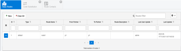
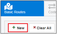
- Click New to add a new route, as shown in the following image.
The New Basic Route dialog opens, as shown in the following image.
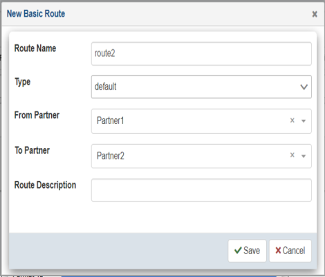
- Enter the information for the trading partner route you are
creating, as required.
The following table lists and describes the properties of the New Route dialog. An asterisk (*) character indicates a required property.
Property
Description
Route Name*
Unique name for the route.
Type
Specify a predefined type (optional).
From Partner*
Initializing partner from which the message is being received.
To Partner*
Destination partner to whom the message is sent.
Route Description
Optional description for the route.
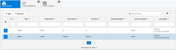
- Click Save when you
are finished.
The new route is added, as shown in the following image.
Code Substitution
Code substitution enables the translation of identifying elements from one partner to another through a business route. Each partner system within a business route has a domain and code where the combination is unique. They are used to determine where a message came from and where it should be routed to. Both partners in a business route know the unique identifiers of each other, even though they might not be the same. For example, Partner 1 knows itself as A and sends a message to partner B. The receiving partner knows A as X and knows itself as Y. The business route enables the application to convert A to X and B to Y to send the message correctly. The sending partner sends the message from A to B, but the receiving partner receives the message as X to Y, as illustrated in the following diagram.
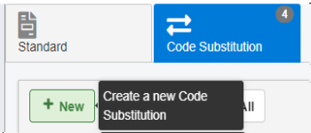
The Code Substitution tab can be accessed from the Advanced Routes and Basic Routes pages in the console, as shown in the following image.
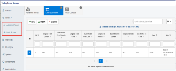
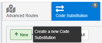
To create a new code substitution for a business route, select the business route, and then click New, as shown in the following image.
The New Code Substitution dialog opens, as shown in the following image.
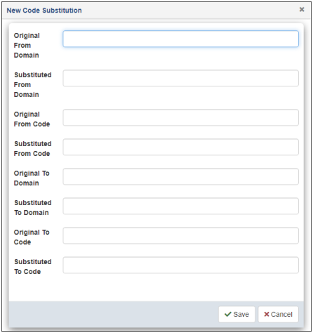
Provide the necessary information, and then click Save.
To import a Code Substitution, refer to Import UI.
For other menu items, refer to Menu Options.
Route Contacts
The route contacts for the business route enables the configuration of the contacts for the business route. The selection of contacts which can be added to the business route contacts is limited to the list obtained from the two partners associated with the business route.
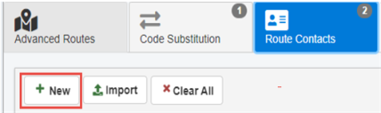
The Route Contacts tab can be accessed from the Advanced Routes and Basic Routes pages in the console, as shown in the following image.
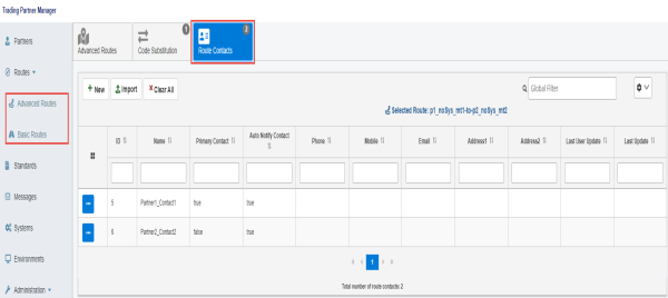
To add a contact to a business route, select the business route, and then click New, as shown in the following image.
The New Advanced Route Contact dialog opens, as shown in the following image.
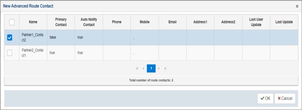
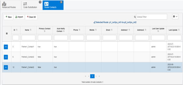
Select an available contact from the table, and then click OK. You are returned to the Route Contacts tab, which is now updated with the selected contact, as shown in the following image.
To import a Route Contact, refer to Import UI.
For other menu items, refer to Menu Options.
Standards
The message standard is the name of a given standard for message formats, such as HL7 or CIDX. A message standard consists of message formats, which are specific sub-types or versions of a standard. In turn, message formats consist of specific message types. The following diagram provides an overview of the message standard component. For more information about message formats and message types, see Messages.
One of the key features of standards is the ability to define not only a user-defined standard to group application specific messages, but also to create standard code substitutions.
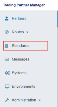
To access the Standards page, click Standards from the left navigation pane in the console, as shown in the following image.
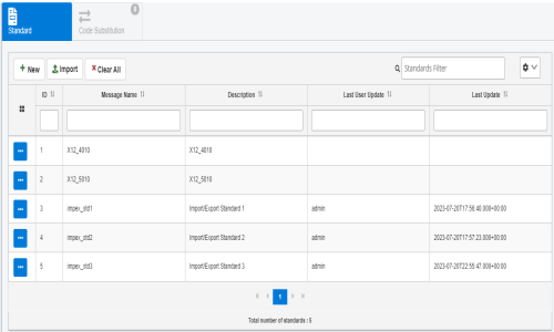
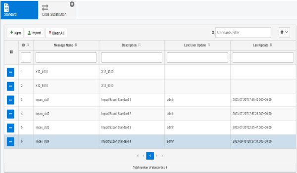
The Standards page opens, which lists all of the standards currently defined, as shown in the following image.
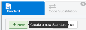
To define a new standard, click New, as shown in the following image.
The New Standard dialog opens, as shown in the following image.
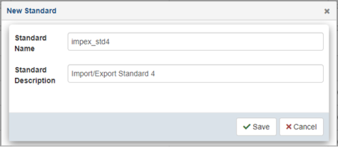
Provide a name and description of the standard, which makes this standard available to the message format definition process. When you are finished, click Save.
The new standard that you defined is added to the table in the Standard tab, as shown in the following image.
You can also import a previously-exported Standard.
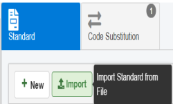
Click Import, as shown in the following image.
The Import Standard dialog opens, as shown in the following image.
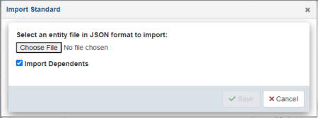
Click Choose Files to select the previously-exported Standard JSON documents.
Select the Import Dependents checkbox to import the Standard along with its dependents.
Click Save to import the Standard along with its dependents and refresh the table.
For other menu items, refer to Menu Options.
Standards Code Substitution
When sending a message from one system to another, it is likely that the two systems may use different message standards or formats. The application processing the message (the message engine), takes into account the format and converts the message from an inbound format to an outbound format. However, the content of the message might need to be adjusted for specific values. This is where the standard code substitution is used.
For example, you may have a use case where the Product_Code field must be converted from B_001 to BUN before the message can be processed by a receiving system.
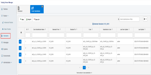
On the Standards page, which displays the Standard tab by default, select an available standard from the table. Then, click the Code Substitution tab, as shown in the following image.
To define a new code substitution, click New, as shown in the following image.
The New Code Substitution dialog opens, as shown in the following image.
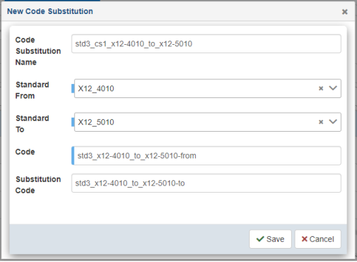
Provide values for the available properties according to your requirements and then click Save.
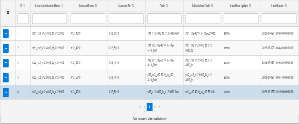
The new code substitution that you defined is added to the table in the Code Substitution tab, as shown in the following image.
You can also import a previously-exported Code Substitution.
Click Import, as shown in the following image.
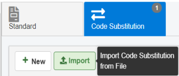
The Import Code Substitution dialog opens, as shown in the following image.
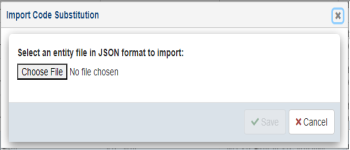
Click Choose Files to select the previously-exported Code Substitution JSON documents.
Click Save to import the code substitution and refresh the table.
For other menu items, refer to Menu Options.
Messages
This section provides an overview on message format and message type.
Message Format Overview
A message format is a specific version or a sub-type of a message standard. Message format is used to group specific message types. For example, if message standard is CIDX, then the message format can be CIDX202 (version 2.02). The following diagram illustrates a message format component.
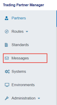
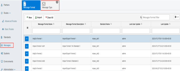
To access the Messages page, click Messages from the left navigation pane in the console, as shown in the following image.
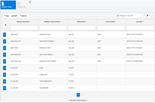
The Messages page opens, and displays the Message Format tab by default, which lists all defined message formats, as shown in the following image.
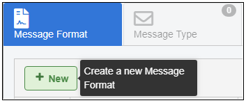
To add a new message format, click New, as shown in the following image.
The New Message Format dialog opens, as shown in the following image.
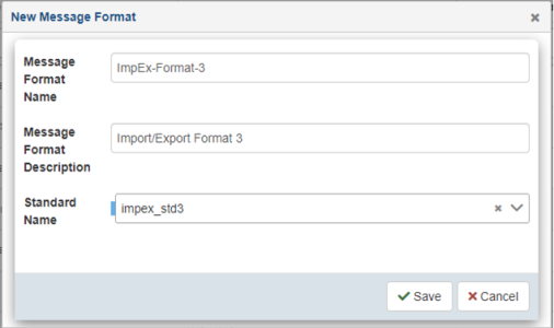
Provide a name, description, and select an associated standard from the drop-down list. When you are finished, click Save.
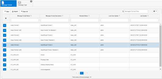
The new message format that you defined is added to the table, as shown in the following image.
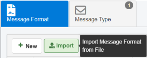
To import message format from previously exported Message Type JSON documents, click Import, as shown in the following image.
The Import Message Format dialog opens, as shown in the following image.
Click Choose Files to select previously exported Message Type JSON documents.
Click Save to import the message type data and refresh the table.
Message Type Overview
The message type is a specific type of message within the format. For example, Shipnotice is a message type within the CIDX202 format, which is associated with the CIDX standard. The message type can also be associated with a specific schema to define the structure and validation for the message. The message type values can be used by a processing system to identify which transforms can be used to convert the message before sending it to the destination system. It is also used in conjunction with unique identifiers for partner systems to determine the routing of the message.
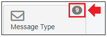
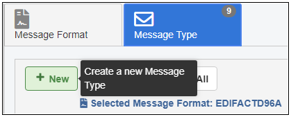
To review and create message types, ensure the Message Format tab is selected on the Messages page. Select an available message format from the table, and then click the Message Type tab, as shown in the following image.
To add a new message type, click New, as shown in the following image.
The New Message Type dialog opens, as shown in the following image.
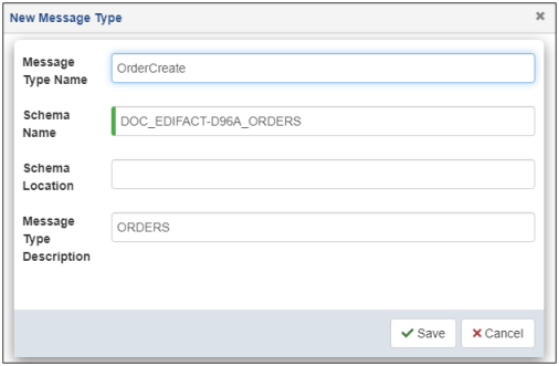
Provide a message type name, schema name with an optional location, and description. When you are finished, click Save.
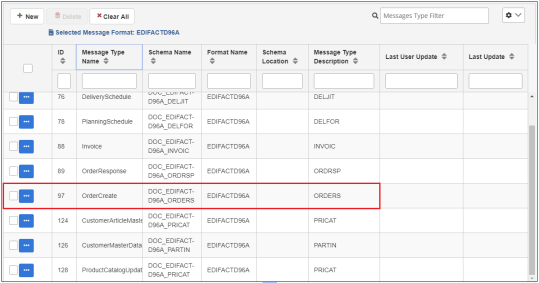
The new message type that you defined is added to the table, as shown in the following image.
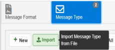
To import a previously exported message type, click Import, as shown in the following image.
The Import Message Type dialog opens, as shown in the following image.
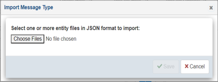
Click Choose Files to import previously exported Message Type JSON documents.
Click Save to import the message type data and refresh the table.
The options menu in a message type corresponding row has the Export option.
Select Export to download the selected message type's data as a JSON document.
Systems
Systems are physical end-systems, such as machines or applications (iWay Service Manager (iSM) channels), that can send messages to the processing engine. The systems are directly mapped to iSM components, such as adapters, channels, and listeners, to make them accessible during iWay TPM runtime to the application. Before a system is defined, the appropriate iSM component must be created and made available in iSM. In some instances, systems can also represent a logical system used for routing messages, in which case there is no iSM component associated with the defined system. A system can only be in one environment at a time.
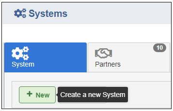
To access the Systems page, click Systems from the left navigation pane in the console, as shown in the following image.
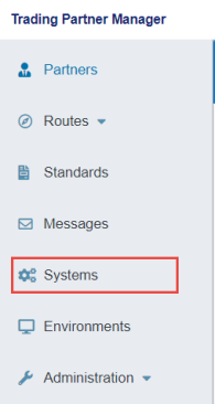
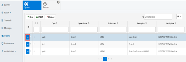
The Systems page opens in the console, as shown in the following image.
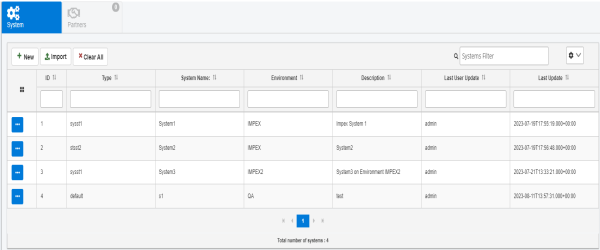
The System tab is selected by default, which lists all the defined systems and enables the creation of new systems for iWay TPM use.
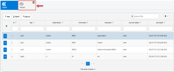
To review the partners that are associated with a specific system, ensure the System tab is selected on the Systems page. Select an available system from the table, and then click the Partners tab, as shown in the following image.
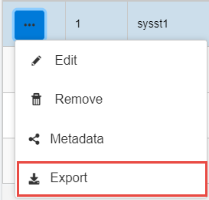
To edit an existing system, click the options menu to the left of the system in the corresponding row, as shown in the following image.
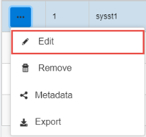
Click Edit from the menu, as shown in the following image.
The Edit System dialog opens, as shown in the following image.
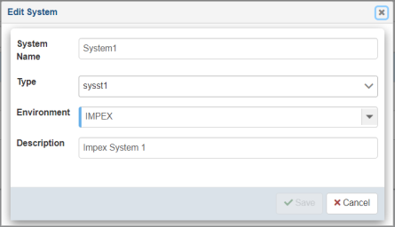
When you are finished editing the system information, click Save.
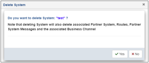
To delete an existing system, select the system and click Remove from the options menu, as shown in the following image.

The Delete System confirmation dialog opens, as shown in the following image.
To download the selected system's data as a JSON document, select the system and click Export from the options menu.
Create a System
To create a system using the console:
- Procedure
- From the Systems page, select the System tab, and then click New, as shown in the following image.
The New System dialog opens, as shown in the following image.
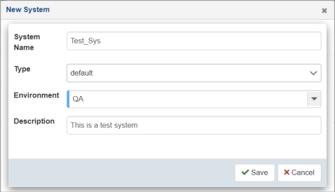
- Enter the information for the system you are creating.
The following table lists and describes the properties in the Create New System dialog.
Property
Description
System Name
Unique name for the system.
Type
Specify a predefined type (optional).
Environment
Environment to which this system applies (for example, DEV, QA, PROD).
Description
Optional description for the system being created.
- Click Save.
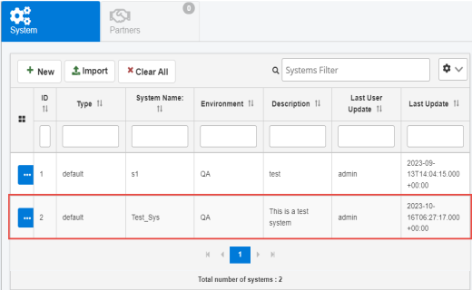
The new system is added to the table in the System tab, as shown in the following image.
Import System
To import a system using the console:
- Procedure
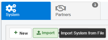
- From the Systems page, select the System tab, and then click Import, as shown in the following image.
The Import System dialog opens, as shown in the following image.
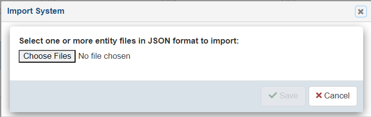
-
Click Choose Files to select previously exported System JSON documents.
-
Click Save to import the system data and refresh the table.
Environments
The main environments page allows the management of the environments defined in iWay TPM. With different environments, you can organize an infrastructure. Systems and business routes can be associated to an environment. This is a valuable option for applications which share the same database repository to store information for multiple environments such as developer and quality assurance environments. However, it is always recommended to have a separate database repository for the production environment, rather than using this shared repository approach.
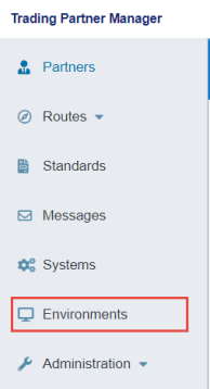
To access the Environments page, click Environments from the left navigation pane in the console, as shown in the following image.
The Environments page opens in the console, as shown in the following image.
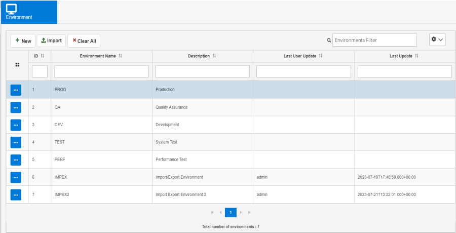
The Environments page enables the management and creation of pre-defined and new environments for the application.
You can also import previously-exported Environment JSON documents using the Import button. Refer to Import UI for more information. For other menu items, refer to Menu Options.
Administration
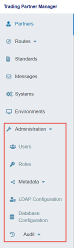
The Administration menu in the console allows administrators to add, delete, and edit other users. Administrators can also designate various roles to managed users. The Administration menu is designed to provide an audit trail of user login activity, as well as various settings and metadata management. To access the Administration menu, expand Administration in the left navigation pane, as shown in the following image.
Users
The Users section allows administrators to add, delete, and edit other users.
Create a New User
To create a new user:
- Procedure
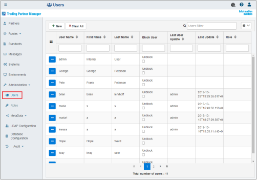
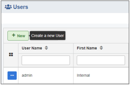
- From the Administration menu, click Users, and then click New, as shown in the following image.
The New User dialog opens, as shown in the following image.
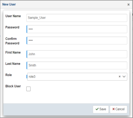
The following table lists and describes the properties in the New User dialog.
Property
Description
User Name
Unique name of the user.
Password
Password of the user.
Confirm Password
You must re-enter the password in this field.
First Name
First name of the user.
Last Name
Last name of the user.
Role
Select an available role from the drop-down list to be assigned to the user.
Block User
If selected, user access to iWay TPM is blocked without deleting the user.
- Provide the required information for the new user and click Save.
The new created user appears in the screen of available users.
-
To edit an existing user, select the user and then click Edit from the options menu, as shown in the following image.
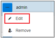
The Edit User dialog opens. Modify the user properties as required and then click Save.
-
To delete an existing user, select the user and then click Remove from the options menu, as shown in the following image.
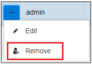
The Delete User confirmation dialog opens. Click Yes to confirm the removal of the selected user.
Roles
The Roles section allows administrators to add, delete, and edit roles which can be assigned to the users.
Create a New Role
To create a new role:
- Procedure
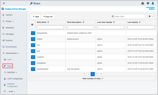
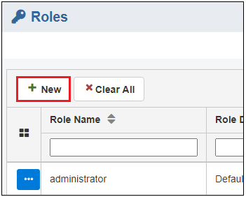
- From the Administration menu, click Roles, and then click New, as shown in the following image.
The New Role dialog opens, as shown in the following image.
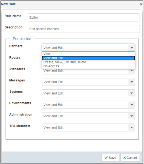
The following table lists and describes the properties in the New Role dialog.
Property
Description
Role Name
Unique name for the role.
Description
Description for the role.
Permissions
Specify the access rights for each area (also represents each tab in the console):
- View. Only view the rights.
- View and Edit. Allows you to view and edit existing information, but not to create or delete.
- Create, View, Edit, and Delete. Full rights to a given tab.
- No Access. Tab is not visible.
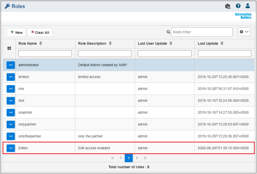
- Provide the required information for the new role and click Save.
The created role appears in the screen of available roles shown below, and is available to be assigned to users.
-
To edit an existing role, select the role and click Edit, as shown in the following image.
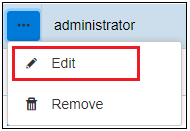
The Edit Role dialog opens. Modify the role properties as required and then click Save.
-
To delete an existing role, select the role and click Delete, as shown in the following image.
The Delete Role confirmation dialog opens. Click Yes to confirm the removal of the selected role.
Note: If a role is associated with any user, you are not able to delete it.
Metadata
The Metadata section allows those users with designated rights to manage metadata nodes and data types for all components within iWay TPM. This area enables the creation or deletion of metadata nodes for a given component such as partner. The created metadata is available for all instances of a component. For example, the PartnerST1 metadata node created for the partner component is available for all partners created, but stores different values specific to a given partner.
The following image shows the Metadata Configuration screen, which can be accessed from the Administration menu.
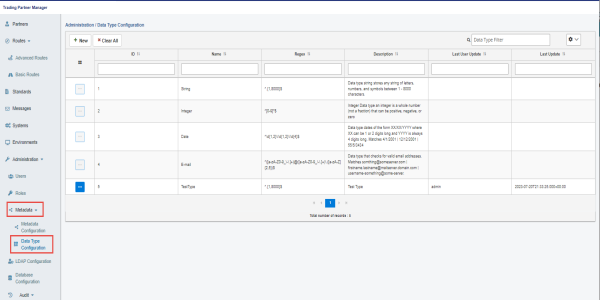
The following image shows the Data Type Configuration screen, which can be accessed from the Administration menu.
For more details regarding Metadata Configuration, refer to Extensible Metadata and Metadata Management.
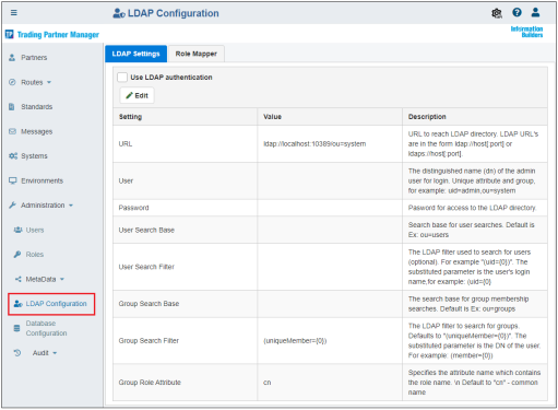
LDAP Configuration
The LDAP Configuration section allows system administrators to enable and configure LDAP authentication with iWay TPM. The LDAP Settings tab is selected by default and shows the current LDAP configuration properties, as shown in the following image.
To enable LDAP, click Use LDAP authentication, as shown in the following image.
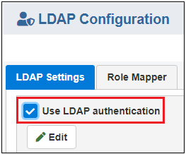
To edit LDAP settings and test your connection, click Edit.
The Edit LDAP Properties dialog opens, as shown in the following image.
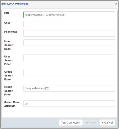
Modify your LDAP properties as required, click Test Connection to verify, and then click Save.
The following message displays when the LDAP connection test is successful:

The following message displays when the LDAP connection test is unsuccessful:

In the LDAP Configuration section, the Role Mapper tab allows you to map LDAP groups with iWay TPM roles, as shown in the following image.
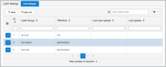
To create a mapping, click New.
The New Group Mapper dialog opens, as shown in the following image.
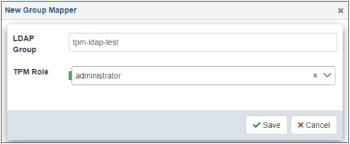
Type your LDAP Group name in the field and select a corresponding role from the TPM Role drop-down list. Click Save.
You are returned to the Role Mapper tab where your new mapping is added to the table.
To edit or delete a role mapping, click a specific row in the table and select Edit or Remove from the options menu, as shown in the following image.
For more information on configuring LDAP, see Configuring and Enabling LDAP.
Database Configuration
The Database Configuration section allows system administrators to review, modify, and test connection settings for the iWay TPM database that has been configured.
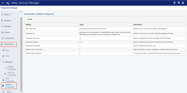
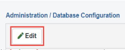
To edit your database settings and test your connection, click Edit, as shown in the following image.
The Edit Database Properties dialog opens, as shown in the following image.
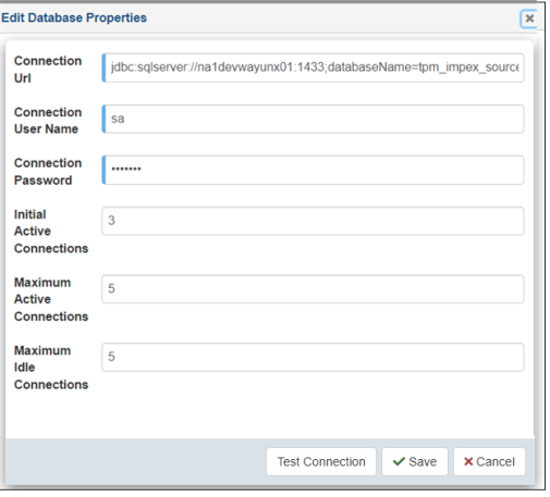
Modify your database properties as required, click Test Connection to verify, and then click Save.
The following message displays when the database connection test is successful:
The following message displays when the database connection test is unsuccessful:
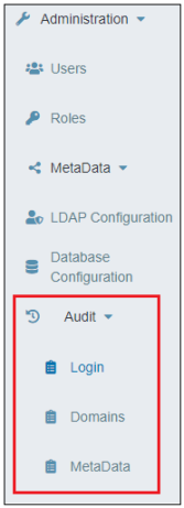
Audit
The Audit section in the Administration menu is organized by three areas, which allow administrators to monitor user login activity, domains, and metadata in iWay TPM.
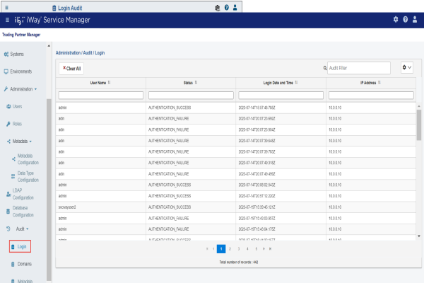
Login Audit
The Login Audit page provides the user name, the login status, login date/time, and IP address.
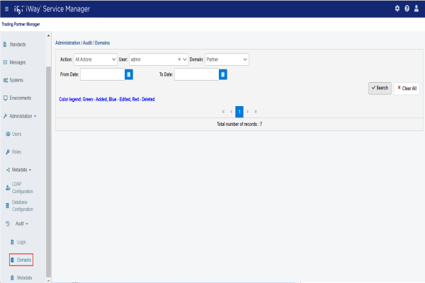
Domains Audit
The Domains Audit page allows you to review which domain (for example, Partner) was added, modified, or deleted based on a specific user ID. You can also specify a time frame (From Date/To Date) to narrow your search.
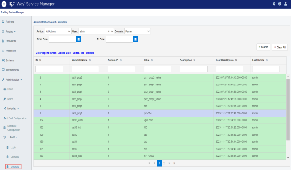
Metadata Audit
The Metadata Audit page allows you to review which metadata nodes were added, modified, or deleted based on a specific user ID and domain (for example, Partner). You can also specify a time frame (From Date/To Date) to narrow your search.
Extensible Metadata
Extensible metadata is one of the key features of iWay Trading Partner Manager. It enables the application to extend the definition of any component (for example, partner, system, message, and so on) to contain application specific attributes. The metadata is defined in the console and then accessed by an application at runtime through the standard iWay TPM function calls, for example to provide additional attributes to facilitate proper routing and message processing. For example, a ReceiverID metadata field can be associated with a partner, so when the application receives an EDI message, it can perform a look up to retrieve the partner information based on the ReceiverID from the incoming message and continue message processing.
Metadata Management
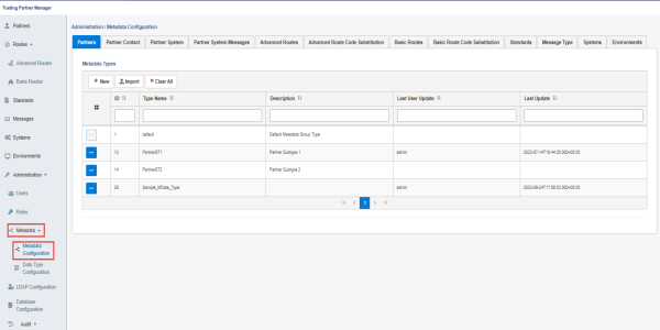
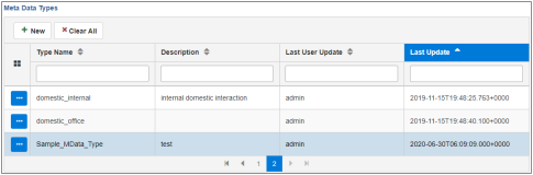
Metadata management is performed through the Administration menu of the console. Once the Administration menu is accessed, a user (with proper permissions) can expand the Metadata menu and select the Metadata Configuration submenu. The Metadata Configuration page opens and displays a set of sub-tabs where each tab represents a component (for example, Partners, Systems, and so on), as shown in the following image.
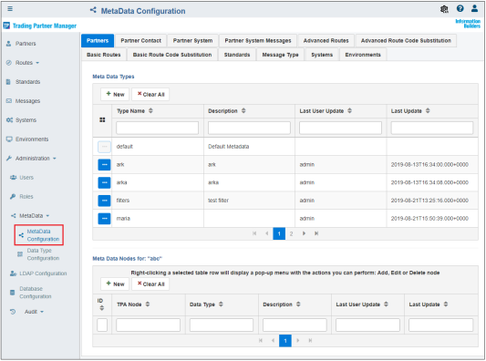
You can define a metadata type for each component, and further extend this metadata by defining metadata nodes for each type. You can also import any previously exported metadata type JSON documents using the Import functionality.
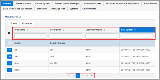
You can easily manage extensive lists of metadata by using the available controls in each table (for example, sorting, filtering, and scrolling), as shown in the following image.
Create a Metadata Type
To create a metadata type:
- Procedure
- On the Metadata Configuration page, click the sub-tab for the component you wish to create the metadata type (for example, Partners).
- Click New in the Metadata Types table, as shown in the following image.
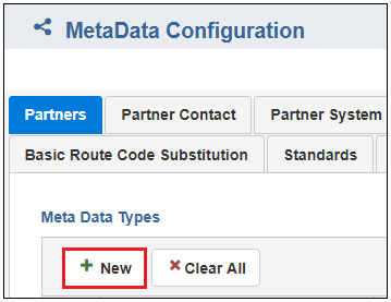
The New Metadata Type dialog opens, as shown in the following image.
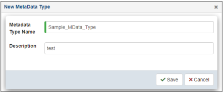
- Specify a name for the new metadata type, which is required, and a brief description (optional).
- Click Save.
The new metadata type is added to the table, as shown in the following image.
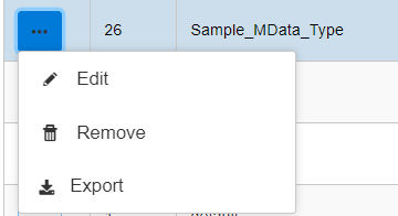
- The ellipsis menu has three options. To edit or delete a metadata type,
select the metadata type and click Edit or Remove from the options, as shown in the following image. Click Export to download the selected metadata type's data as a JSON document.
Import Metadata Type
To import metadata type:
- Procedure
- On the Metadata Configuration page, click the sub-tab for the component you want to import the metadata type (for example, Partners).
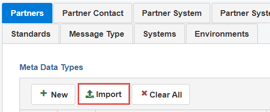
- Click Import in the Metadata Types table, as shown in the following image.
The Import Metadata Type dialog opens, as shown in the following image.
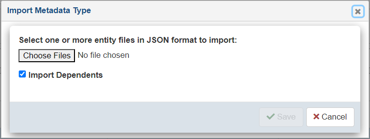
- Click Choose Files to select previously exported Metadata Type JSON document. You can select one to N number of documents. Select the checkbox Import Dependents if the document has dependents and you want to import them.
- Click Save to import the metadata type and refresh the table.
Create a Metadata Node
To create a metadata node:
- Procedure
- On the Metadata Configuration page, click the sub-tab for the component you wish to create the metadata type (for example, Partners).
- Select a metadata type from the Metadata Types table.
- Click New in the Metadata Nodes for (selected metadata type) table, as shown in the following image.
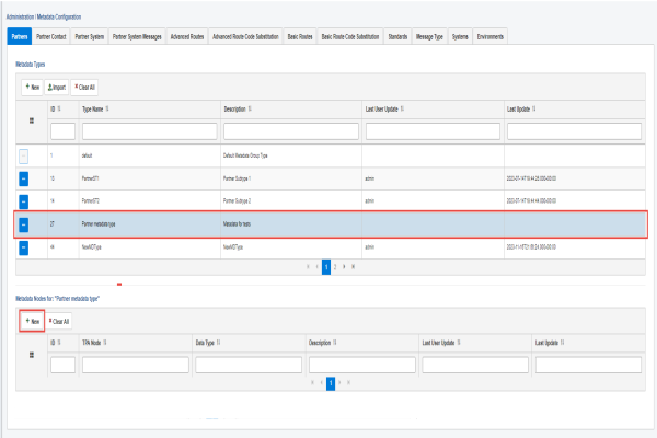
The Add TPA Nodes dialog opens, as shown in the following image.
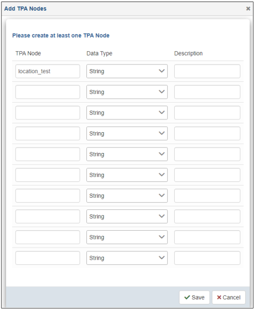
- Specify a name for the TPA node, select an available data type from the drop-down list, and a description (optional).
Note: You can define multiple TPA nodes if required, but you must define at least one.
- Click Save.
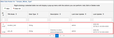
The newly created metadata node displays in the Metadata Nodes for (selected metadata type) table, as shown in the following image.
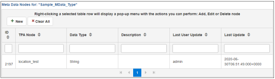
This metadata node is now available for all partner objects and can be assigned partner specific values.
For more information on partner assignment, see Assigning Metadata Values.
Delete a Metadata Node
To delete a metadata node, right-click the metadata node you wish to delete in the Metadata Nodes for (selected metadata type) table and select Delete TPA Node from the menu, as shown in the following image.
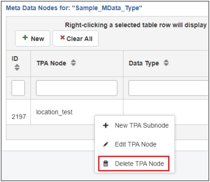
The Delete TPA Node confirmation dialog opens, as shown in the following image.
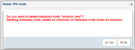
Click Yes to confirm or No to cancel.
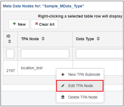
Edit a Metadata Node
To edit a metadata node, right-click on the metadata node you wish to edit in the Metadata Nodes for (selected metadata type) table and select Edit TPA Node from the menu, as shown in the following image.
The Edit TPA Node dialog opens, as shown in the following image.
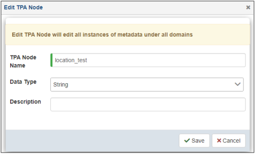
Modify the metadata node as required and click Save.
When you rename the node, the new name affects all component instances referencing the renamed metadata node as well as any application already using the node. As a result, use this option with caution.
Group Metadata Nodes
When dealing with extensive metadata, it is recommended and useful to group the metadata fields rather than having a list of all the nodes. The grouping is visual only and access to any node within a tree is the same at runtime and does not require tree navigation as the metadata node is being retrieved by name, and should still be unique.
To group metadata nodes:
- Procedure
- Right-click an existing metadata node and select New
TPA Subnode from the menu, as shown in the following image.
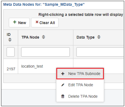
The New TPA Subnode dialog opens, as shown in the following image.
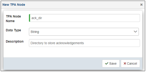
- Specify a name (for example, ack_dir), select an available data type from the drop-down list, and provide a description (optional).
- Click Save.
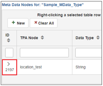
- Click the right arrow (>) to expand the row.
The new node (ack_dir) appears as a subnode of the metadata node you created (in this case, location_test), as shown in the following image.
You can add additional nodes or groups of nodes as required.
Assigning Metadata Values
Metadata nodes are managed by the administrator who has access to the Metadata section in the Administration menu. The actual assignment of values to the metadata nodes is done by someone who has access to the specific component and proper edit rights. The user accessing and managing the components does not require full administration rights.
The following example uses a Partner to demonstrate the process of metadata assignment. The same approach can be followed and used for any other component, such as System, Partner System, Partner Contact, and so on.
To assign a metadata value to a specific component, such as Partners, navigate to the corresponding tab (for example, Partners). Select a partner and click Metadata from the options menu, as shown in the following image.
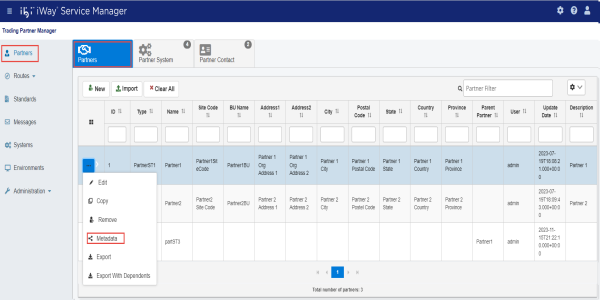
A metadata management screen opens, providing access to all metadata nodes available for the selected component, as shown in the following image.
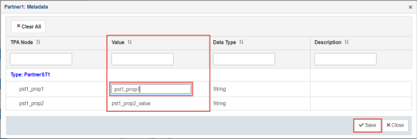
To edit a metadata value, click the corresponding row in the Value column and enter a value in the field.
Once you are done, click Save to save your changes.
After the metadata values have been added to all required nodes, click the X icon (Close) in the upper-right corner to exit the screen. The metadata updates can be viewed on the component tab and are available in the runtime application.
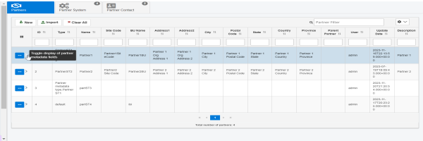
To view the updates, you can go to the console, select any component, and hover over the right arrow as shown in the following image.
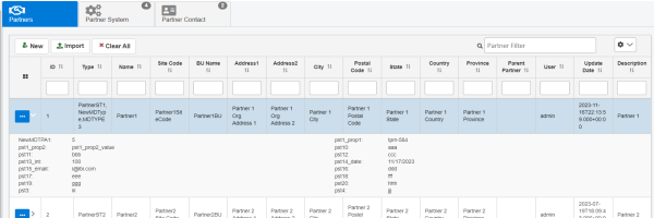
If you click the arrow, the metadata fields are displayed as follows.
Adding Data Types
You can add new data types, which can be specified during the configuration of metadata nodes.
To add a data type:
- Procedure
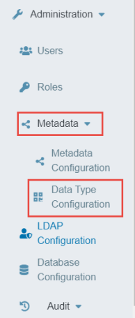
- Expand Metadata in the Administration menu and click Data Type Configuration, as shown in the following image.
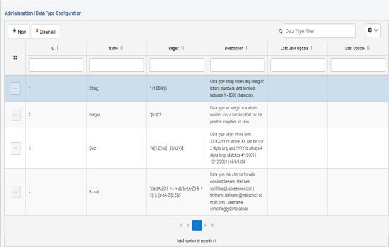
The Data Type Configuration page opens, as shown in the following image.
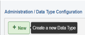
- Click New, as shown in the following image.
The New Data Type dialog opens, as shown in the following image.
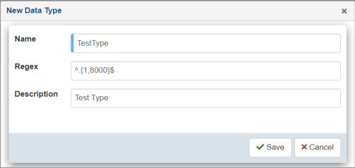
- Specify a name, regex value, and a description (optional) for your new data type.
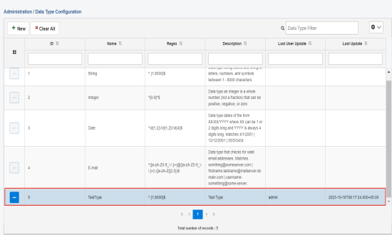
- Click Save.
The new data type is added to the table, as shown in the following image.
- To edit or delete a data type, click a specific row in the table and select Edit or Remove from the options menu, as shown in the following image.