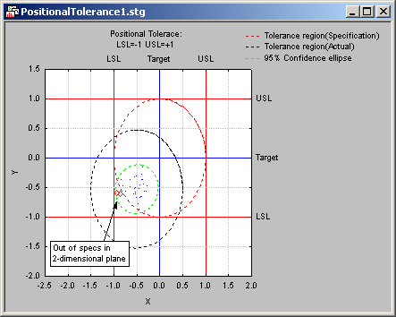
Capability Ratios for True Position - Introductory Overview
Some manufacturing processes, and the allowable tolerances that define acceptable quality, can best be summarized by the metaphor of hitting a target.
For example, when drilling holes at specific locations, the quality requirement is best defined by circles around the desired locations; every time that a hole is drilled outside the acceptable quality (circle), the respective part is rejected.
Tolerances (specification limits) defined as a circle in the two-dimensional plane are also called positional tolerances. For such processes, the standard capability values (ratios) are not appropriate, because while the process may be within-specs on each individual dimension, the respective point (in the two-dimensional plane) may be unacceptably far away from the desired goal (point).

For example, in the illustration above, there are two points that, when considering the +/-1 USL/LSL specification limits for each dimension separately, would not be out of specs. However, if the specs are defined as a circle around the origin {0,0}, with a radius of 1, then these two points would be rejected.
The Computational Details topic shows the formulas that can be used to compute process capability indices for processes with positional (circular) specifications such as this; these formulas have the same interpretation as do the standard univariate capability indices computed by the Process Analysis Procedures module, i.e., they can be interpreted as the number of times that the normally occurring process variability (in two-dimensional space) will "fit" inside the lower and upper specification limits.
