
Installing Data Channels
TIBCO® ModelOps supports two kinds of data channels: sources and sinks. ModelOps currently supports two types of data channels: File and Kafka channels. The Data Channels page provides detailed information about data channels. This page will provide further details about installing data channels and any prerequisite work involved.
Contents
Creating Data Channels
A data channel configuration describing the data channel has to be created before a data channel can be deployed. The ModelOps UI allows users to create data channel configurations. Data channel configuration includes data channel type, data channel schema, and other information specific to data channel type (topic and broker information for Kafka channels, file-encoding, other parser options for File channels, connection URL, SQL query and other database options for JDBC channels). See Kafka Channels, File Channels and JDBC Channels for details.
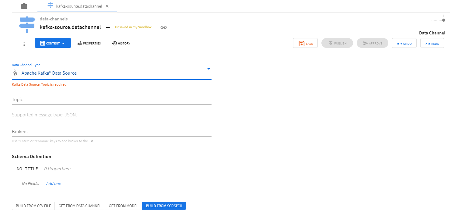
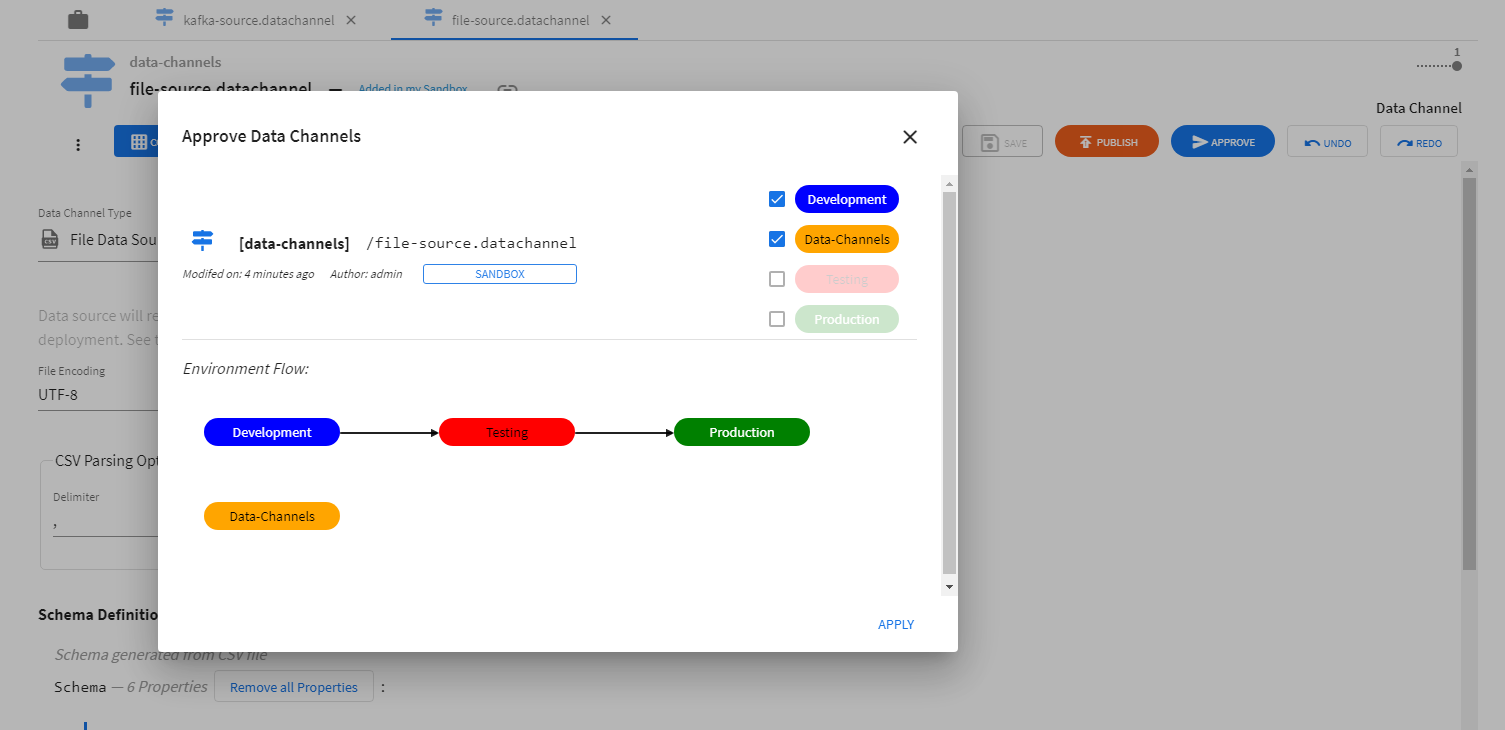
Data channel configurations have to be approved for use in environments before data channels can be successfully deployed.
Deploying Data Channels
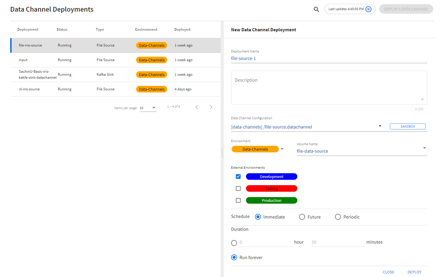
After creation and approval, data channel configurations can be deployed using the Deployments page. The Deployments page allows the user to: * provide a name for the deployment * select the configuration to be deployed * select environments for deployment * the schedule and duration for the deployment * data channel specific information (like Volume Name for File channels)
Kafka Channels
Kafka channels connect to running instances of Apache Kafka® brokers and a specific topic to read or write messages. The broker and topic information must be provided on the channel configuration page where the data channel schema is also specified.
ModelOps supports the following broker string specifications based on the authentication type. Examples for each authentication type are provided below.
No Authentication
This is a very simple no authentication broker string containing the server URL including the port number.
example.com:9092
omnibus-01.srvs.cloudkafka.com:9094
Note: The ModelOps brokers option supports multiple broker strings placed one below the other.
PLAIN
A simple username/password authentication mechanism i.e. PLAIN, or SASL/PLAIN, is typically used with TLS for encryption to implement secure authentication. More details are available here, Configuring PLAIN.
An example of a PLAIN authentication type broker string for ModelOps is shown below.
test.com:9094[security.protocol=SASL_PLAINTEXT|sasl.mechanism=PLAIN|sasl.jaas.config=org.apache.kafka.common.security.plain.PlainLoginModule required username="admin" password="********";]
SCRAM
Salted Challenge Response Authentication Mechanism (SCRAM) or SASL/SCRAM, addresses the security concerns with traditional PLAIN user/password authentication mechanism. More details are available here, Configuring SCRAM.
An example of a SCRAM authentication type broker string for ModelOps is shown below.
test.com:9094[security.protocol=SASL_SSL|sasl.mechanism=SCRAM-SHA-256|sasl.jaas.config=org.apache.kafka.common.security.scram.ScramLoginModule required username="admin" password="********";]
Note: The ModelOps broker strings for both PLAIN and SCRAM type authentication contains a list of pipe separated authentication strings to match the underlying Kafka Adapter Brokers property. Please refer to the Kafka Adapter properties for more details, Kafka Consumer Adapter
File Channels
File channels read data from, and write data to, CSV files. File data source/sink channel configurations contain information in addition to the common data channel properties like type and schema information.
For File Sources, the following additional properties are required:
- File Encoding: encoding to be used for file read operations
- Delimiter: character to be used as delimiter while parsing CSV records
- Has Header Row: flag indicating the presence of a header row
For File Sinks, the following additional properties are required:
- File Encoding: encoding to be used for file read operations
- Quote Mode: defines quoting behavior when writing CSV records
File sources and sinks need “Volume Name” information to be provided during deployment. Persistent Volume Claims available in a given namespace are provided as options for the “Volume Name” field.
AKS
Persistent Volume Claims (PVCs) represent storage requests from a user. PVCs allow usage of abstract storage that a cluster administrator might have provisioned. PVCs consume storage resources through Persistent Volumes (PVs). PVs allow abstraction of storage provising and consumption.
PVs and PVCs together provide a mechanism that let File Sources and Sinks read from, and write to, files shares in various kinds of storage (including cloud-provider-specific storage systems). A File Source deployment instance will read data from a folder named <file-source-deployment-name>/<user-name> in the file share (through the specified PVC) and stream data to scoring pipelines deployed by <user-name> that connect to <file-source-deployment-name>. A File Sink deployment will write data being sent from scoring pipelines deployed by <user-name> that connect to <file-sink-deployment-name>.
Example: PV and PVC Setup
There are several ways to create PVs and PVCs for use with File Source and Sink deployments. The following examples demonstrates one way of creating them using Azure File Shares. The following example assumes that the following are available or true:
- an Azure storage account name (<account-name>) and key(<account-key>)
- access to the
kubectlcommand line tool using the appropriate context
Step-1: Creating a Kubernetes Secret to access storage
The Azure storage account name and key can be stored as a Kubernetes Secret for use in the creation of persistent volumes. Create the following configuration file.
create-storage-secret.yaml
apiVersion: v1
kind: Secret
metadata:
  name: <storage-secret-name>
type: Opaque
data:
  azurestorageaccountname: <base-64-encoded-account-name>
  azurestorageaccountkey: <base-64-encoded-account-key>
To use the create-storage-secret.yaml file, run the following command:
kubectl apply -f create-storage-secret.yaml --namespace datachannels
Step-2: Creating a persistent volume that maps to a file share
The next step is to create Kubernetes Persistent Volumes that map to the file shares created in Azure storage. Create the following configuration file (adapted from this example).
create-persistent-volume.yaml
apiVersion: v1
kind: PersistentVolume
metadata:
  name: pv-for-source
  labels:
    usage: pv-for-source
  annotations:
    description: "A persistent volume for file sources"
spec:
  capacity:
    storage: 20Gi
  accessModes:
    - ReadWriteMany
  azureFile:
    secretName: storage-secret-name
    shareName: data-file-share
    readOnly: false
To use the create-persistent-volume.yaml file, run the following command:
kubectl apply -f create-persistent-volume.yaml
Step-3: Creating a persistent volume claim that uses a persistent volume
The next step is to create Kubernetes Persistent Volume Claims that use Persistent Volumes. Create the following configuration file (adapted from this example).
create-persistent-volume-claim.yaml
apiVersion: v1
kind: PersistentVolumeClaim
metadata:
  name: pv-for-source
  annotations:
    description: "A persistent volume claim for file sources"
    volume.beta.kubernetes.io/storage-class: ""
spec:
  accessModes:
    - ReadWriteMany
  resources:
    requests:
      storage: 20Gi
  selector:
    matchLabels:
        usage: pv-for-source
To use the create-persistent-volume-claim.yaml file, run the following command:
kubectl apply -f create-persistent-volume-claim.yaml --namespace datachannels
pv-for-source will now become available as an option for the Volume Name field in Data Channel Deployments page.
EKS
EKS File-channels flow consist of below stages:
1. Create EFS Storage
Amazon Elastic File System (Amazon EFS) provides a simple, scalable, fully managed elastic EFS file system for use with AWS Cloud services and on-premises resources.
To create the EFS storage follow the simple steps:
Step 1: Login to the AWS console and search for the EFS service. Click on the “Create file system”

Step 2: Add EFS Storage name and select the VPC where EKS cluster is hosted. Click on the create button

Note: VPC group should be the same for EFS and EKS cluster.
Step 3: Select the newly created EFS storage

Step 4: Once the Elastic File system is in available state, in the network tab a new IP address will be assigned per Availability Zone. Select the same Security Group assigned to the EKS cluster

2. Create SFTP Server
AWS has provided a service called “AWS Transfer Family”. Using "AWS Transfer Family service, we can set up a SFTP server. The File Transfer Protocol is a standard communication protocol used for the transfer of computer files from a client to a server on a computer network. FTP is built on a client–server model architecture using separate control and data connections between the client and the server.
To configure the SFTP server, follow the simple steps :
Step 1: Login to the AWS console and search for the “AWS Transfer Family” service. Click on “Create Server”

Step 2: Select “SFTP” option and click on “next”

Step 3: Select identity provider as “Service Managed” and click on “next”

Step 4: Select “Publicly accessible” endpoint and click on “next”

Step 5: Select “Amazon EFS” as a domain and click on “next”

Step 6: Keep the default additional details and click on “next”

Step 7: Review the details and click on create
Step 8: Now, create a Role with below two policies in IAM section
- AmazonElasticFileSystemFullAccess
- AmazonElasticFileSystemClientFullAccess

Step 9: Select the newly created SFTP server in AWS Transfer Family service

Step 10: Click on “Add User”

Step 11: Add the user details
- Username : Add username.
- User ID : It should be “1000”.
- Group ID : It should be “1000”.
- Secondary Group ID : It should be “1000”.
- Role : Select the newly created IAM Role.
- Home directory: Select the EFS storage name that we created in EFS step 2.
- SSH Public key: Generate “ssh-rsa” key on your machine and add public key here.
- Windows Key generation. (https://docs.microsoft.com/en-us/windows-server/administration/openssh/openssh_keymanagement#user-key-generation)
- MacOS/Linux Key generation. (https://docs.rightscale.com/faq/How_Do_I_Generate_My_Own_SSH_Key_Pair.html)


Step 12: Click on “Add”
Step 13: Click on the SFTP server and note the endpoint and username
Note: Copied endpoint will be used as a hostname in SFTP client tool configuration.

3. SFTP Client Tool Setup
Follow the simple steps for SFTP Client tool configuration:
Step 1. SFTP Configuration
- Download and install one of the SFTP client tools (WinSCP or FileZilla).
- Click on the “Site manager”.
- Click on “New Site” and provide a suitable name.
- Select protocol “SFTP”.
- Copy the endpoint from SFTP server and paste it under “Host”.
- Select Logon type “SSH key file”.
- Provide username created at SFTP server.
- Add SSH private key.
- Click on connect

Step 2. Accept the host key for the first time

Step 3. Once the file channel setup is done then the user can see the file-datasource folder as below

4. EFS Configuration at EKS cluster
Configure the EFS storage in EKS cluster.
Follow below steps for configuration:
Step 1: Create a new namespace for hosting the provisioner
Namespace.yaml
  apiVersion: v1
  kind: Namespace
  metadata:
    name: <namespace name>
To apply the above changes, execute below command:
kubectl apply -f Namespace.yaml
Step 2: Create a service account
Service account is used to for deployment of provisioner
Service-Account.yaml
 	apiVersion: v1
	kind: ServiceAccount
	metadata:
  	  name: nfs-client-provisioner
  	  namespace: <namespace name>
To apply the above changes, execute below command:
kubectl apply -f Service-Account.yaml
Step 3: Create a cluster roles
Using this step it grants permission to entire cluster, and provisioner can create those objects
Cluster-Role.yaml
  kind: ClusterRole
  apiVersion: rbac.authorization.k8s.io/v1
  metadata:
    name: nfs-client-provisioner-runner
  rules:
    - apiGroups: [""]
      resources: ["nodes"]
      verbs: ["get", "list", "watch"]
    - apiGroups: [""]
      resources: ["persistentvolumes"]
      verbs: ["get", "list", "watch", "create", "delete"]
    - apiGroups: [""]
      resources: ["persistentvolumeclaims"]
      verbs: ["get", "list", "watch", "update"]
    - apiGroups: ["storage.k8s.io"]
      resources: ["storageclasses"]
      verbs: ["get", "list", "watch"]
    - apiGroups: [""]
      resources: ["events"]
      verbs: ["create", "update", "patch"]
To apply the above changes, execute below command:
kubectl apply -f Cluster-Role.yaml
Step 4: Bind the cluster roles to the service account
This step binds the service account with the cluster role
Cluster-RoleBinding.yaml
  kind: ClusterRoleBinding
  apiVersion: rbac.authorization.k8s.io/v1
  metadata:
    name: run-nfs-client-provisioner
  subjects:
    - kind: ServiceAccount
      name: nfs-client-provisioner
      namespace: <namespace name>
  roleRef:
    kind: ClusterRole
    name: nfs-client-provisioner-runner
    apiGroup: rbac.authorization.k8s.io
To apply the above changes, execute below command:
kubectl apply -f Cluster-RoleBinding.yaml
Step 5: Create roles
Role.yaml
  kind: Role
  apiVersion: rbac.authorization.k8s.io/v1
  metadata:
    name: leader-locking-nfs-client-provisioner
    namespace: <namespace name>
  rules:
    - apiGroups: [""]
      resources: ["endpoints"]
      verbs: ["get", "list", "watch", "create", "update", "patch"]
To apply the above changes, execute below command:
kubectl apply -f Role.yaml
Step 6: Create role binding
Role-Binding.yaml
  kind: RoleBinding
  apiVersion: rbac.authorization.k8s.io/v1
  metadata:
    name: leader-locking-nfs-client-provisioner
    namespace: <namespace name>
  roleRef:
    kind: Role
    name: leader-locking-nfs-client-provisioner
    apiGroup: rbac.authorization.k8s.io
  subjects:
  - kind: ServiceAccount
    name: nfs-client-provisioner
    #replace with namespace where provisioner is deployed
    apiGroup: rbac.authorization.k8s.io
    namespace: <namespace name>
To apply the above changes, execute below command:
kubectl apply -f Role-Binding.yaml
Step 7: Create a EFS provisioner Note: In the below request pass the IP address or DNS name of the EFS server. Refere the screenshot from step 4 of Create EFS Storage
Provisioner.yaml
  kind: Deployment
  apiVersion: apps/v1
  metadata:
    name: nfs-client-provisioner
    namespace: <namespace name>
  spec:
    replicas: 1
    strategy:
      type: Recreate
    selector:
      matchLabels:
        app: nfs-client-provisioner
    template:
      metadata:
        labels:
          app: nfs-client-provisioner
      spec:
        serviceAccountName: nfs-client-provisioner
        containers:
          - name: nfs-client-provisioner
            image: k8s.gcr.io/sig-storage/nfs-subdir-external-provisioner:v4.0.2
            volumeMounts:
              - name: nfs-client-root
                mountPath: /persistentvolumes
            env:
              - name: PROVISIONER_NAME
                value: nfs-storage  # Need to pass this value in next step
              - name: NFS_SERVER
                value: 172.31.27.152 # Pass the NFS IP address
              - name: NFS_PATH
               value: /
        volumes:
          - name: nfs-client-root
            nfs:
              server: 172.31.27.152 # Pass the NFS IP address
              path: /
To apply the above changes, execute below command:
kubectl apply -f Provisioner.yaml
Step 8: Create Storage class which will be used for creating PVCs Pass the provisioner name that was created in Step-7 Storage-class.yaml
  apiVersion: storage.k8s.io/v1
  kind: StorageClass
  metadata:
    name: managed-nfs-storage
  provisioner: nfs-storage # Created in step 7
  parameters:
    archiveOnDelete: "false"
To apply the above changes, execute below command:
kubectl apply -f Storage-class.yaml
Step 9: Create PVC for DataSource and Sink We don’t need to create PV as it gets dynamically provisioned. PVC.yaml
  apiVersion: v1
  kind: PersistentVolumeClaim
  metadata:
    name: datasource
    namespace: datachannels
  spec:
    storageClassName: managed-nfs-storage
    accessModes:
    - ReadWriteMany
    resources:
      requests:
        storage: 10Mi
To apply the above changes, execute below command:
kubectl apply -f PVC.yaml
JDBC Channels
JDBC data source channels connect to running MySQL (8+) or TIBCO Data Virtualization database server instances, execute a given SQL query and stream a result set to connected clients. The connection URL, SQL query and other database related options for configuring a JDBC data source are described in detail here.
The sections below, provide some useful links and tips on installing and running a TIBCO® Data Virtualization server. A specific section on MySQL databases is not provided in this document since MySQL database servers can be installed and made available on the same TDV server. The TDV Client Interfaces Guide provides more details on this. If users want a separate MySQL installation, they can create MySQL databases on cloud platforms like AWS or Azure and configure connections to it using the Server URL, port and other information.
Note: The MySQL server instances created on cloud platforms like Azure or AWS must also be available for access within the same virtual network/subnet as the ModelOps server along with the database port open for access to machines available on this subnet. Opening database ports for public access is highly discouraged due to security concerns.
TIBCO® Data Virtualization server on a Azure Virtual Machine
JDBC data source channels can connect to TIBCO® Data Virtualization (TDV) servers that are installed on Azure Virtual Machines available on the same virtual network/subnet as the ModelOps server.
Required Software Components
TDV provides installers for several Data Virtualization software components as discussed here. The TDV Server is the only required component for connecting a JDBC data source channel to TDV data sources.
Installation Guide
The TDV installation process for,
provide the necessary steps required for running TDV Server or Studio installers.
The complete TDV Installation Guide provides complete information on the installation process.
Web UI
For creating new TDV data sources or views, use the TDV Web UI. This UI is available at URL like below after installing and running a TDV server,
http://<server>:<port>/webui/login
Note: If you are running the TDV Server locally, then you can access the Web UI at:
http://localhost:9400/webui/login
The TDV Web UI User Guide has more information on this.
Port Requirements
By default, a TDV server listens on port 9401 for JDBC/OBDC connections and this port should allow inbound traffic for JDBC connections.
In general, TDV Server must allow inbound traffic on ports 9400-9403 for a successful connectivity with the JDBC data source. Port 9407 should be exposed only when using the TDV server in a cluster configuration. Some TDV port ranges of interest are below.
TDV Ports: 9400-9403, 9405, 9407, 9409
A complete description of TDV ports is available here.
Connection URL
A TIBCO® Data Virtualization (TDV) connection URL can be created using TDV server name, user credentials, data source name and JDBC port (default 9401). After installing a TDV server, the server name can be obtained by running the TDV manager on port 9400.

The data source name can also be obtained from TDV manager Data Sources page,

An example of TDV connection URL,
jdbc:compositesw:dbapi@tdv-8-4-server.ztjbjgj4sqmezmbxdcvp3xzald.bx.internal.cloudapp.net:9401?domain=composite&dataSource=/shared/examples/ds_orders&user=admin&password=*****
Detailed information on configuring the TDV Connection URL is available here.
TIBCO® Data Virtualization server on a Docker Container
With TIBCO Data Virtualization (TDV) 8.5 release, support for the Docker container is also available. Further details can be found here.
As mentioned previously, the TDV container should also be available on a pod created within the same Kubernetes cluster where ModelOps server and JDBC source channels are installed to access data sources available on this TDV container.