
Data Channels
Data channels send and receive records to and from scoring pipelines.
Details on data channel architecture is in the
Data Channels chapter in the architecture guide.
Details on configuring and deploying data channels is in the Working with Data Channels chapter in the user guide.
This chapter describes additional configuration that must be done in a Kubernetes cluster to support some data channels.
Contents
File Channels
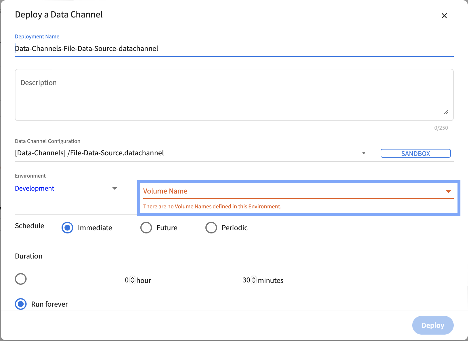
File data channels require a Kubernetes Persistent Volume Claim to be available in the namespace in which they are deployed. Once a persistent volume claim is configured, the volume name is available when deploying a file data channel.
AKS
Persistent Volume Claims (PVCs) represent storage requests from a user. PVCs allow usage of abstract storage that a cluster administrator might have provisioned. PVCs consume storage resources through Persistent Volumes (PVs). PVs allow abstraction of storage provising and consumption.
PVs and PVCs together provide a mechanism that let File Sources and Sinks read from, and write to, files shares in various kinds of storage (including cloud-provider-specific storage systems). A File Source deployment instance will read data from a folder named <file-source-deployment-name>/<user-name> in the file share (through the specified PVC) and stream data to scoring pipelines deployed by <user-name> that connect to <file-source-deployment-name>. A File Sink deployment will write data being sent from scoring pipelines deployed by <user-name> that connect to <file-sink-deployment-name>.
Example: PV and PVC Setup
There are several ways to create PVs and PVCs for use with File Source and Sink deployments. The following examples demonstrates one way of creating them using Azure File Shares. The following example assumes that the following are available or true:
- an Azure storage account name (<account-name>) and key(<account-key>)
- access to the
kubectlcommand line tool using the appropriate context
Step-1: Creating a Kubernetes Secret to access storage
The Azure storage account name and key can be stored as a Kubernetes Secret for use in the creation of persistent volumes. Create the following configuration file.
create-storage-secret.yaml
apiVersion: v1
kind: Secret
metadata:
  name: <storage-secret-name>
type: Opaque
data:
  azurestorageaccountname: <base-64-encoded-account-name>
  azurestorageaccountkey: <base-64-encoded-account-key>
To use the create-storage-secret.yaml file, run the following command:
kubectl apply -f create-storage-secret.yaml --namespace datachannels
Step-2: Creating a persistent volume that maps to a file share
The next step is to create Kubernetes Persistent Volumes that map to the file shares created in Azure storage. Create the following configuration file (adapted from this example).
create-persistent-volume.yaml
apiVersion: v1
kind: PersistentVolume
metadata:
  name: pv-for-source
  labels:
    usage: pv-for-source
  annotations:
    description: "A persistent volume for file sources"
spec:
  capacity:
    storage: 20Gi
  accessModes:
    - ReadWriteMany
  azureFile:
    secretName: storage-secret-name
    shareName: data-file-share
    readOnly: false
To use the create-persistent-volume.yaml file, run the following command:
kubectl apply -f create-persistent-volume.yaml
Step-3: Creating a persistent volume claim that uses a persistent volume
The next step is to create Kubernetes Persistent Volume Claims that use Persistent Volumes. Create the following configuration file (adapted from this example).
create-persistent-volume-claim.yaml
apiVersion: v1
kind: PersistentVolumeClaim
metadata:
  name: pv-for-source
  annotations:
    description: "A persistent volume claim for file sources"
    volume.beta.kubernetes.io/storage-class: ""
spec:
  accessModes:
    - ReadWriteMany
  resources:
    requests:
      storage: 20Gi
  selector:
    matchLabels:
        usage: pv-for-source
To use the create-persistent-volume-claim.yaml file, run the following command:
kubectl apply -f create-persistent-volume-claim.yaml --namespace datachannels
pv-for-source will now become available as an option for the Volume Name field in Data Channel Deployments page.
EKS
EKS File-channels flow consist of below stages:
1. Create EFS Storage
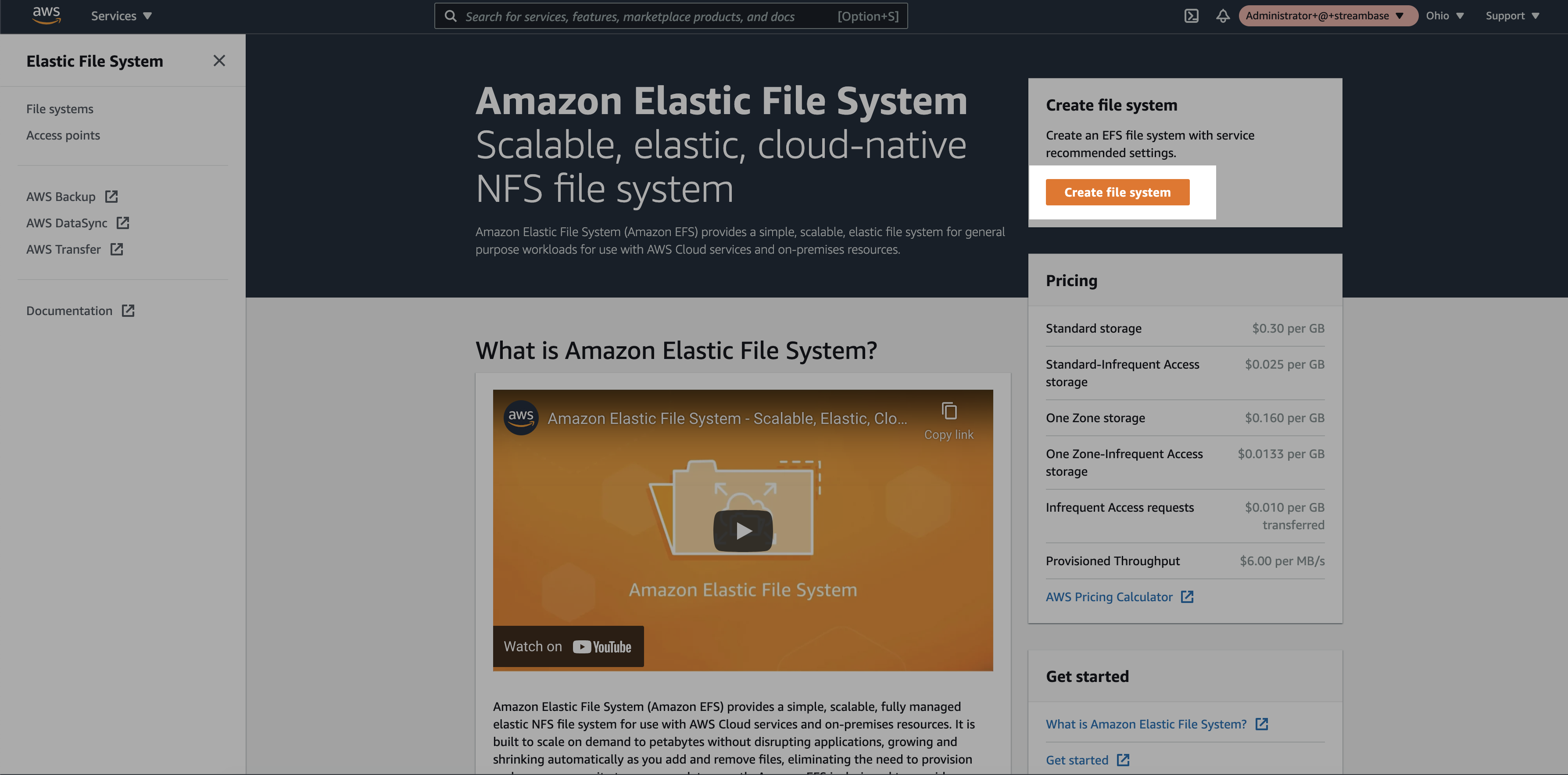
Amazon Elastic File System (Amazon EFS) provides a simple, scalable, fully managed elastic EFS file system for use with AWS Cloud services and on-premises resources.
To create the EFS storage follow the simple steps:
Step 1: Login to the AWS console and search for the EFS service. Click on the “Create file system”
Step 2: Add EFS Storage name and select the VPC where EKS cluster is hosted. Click on the create button
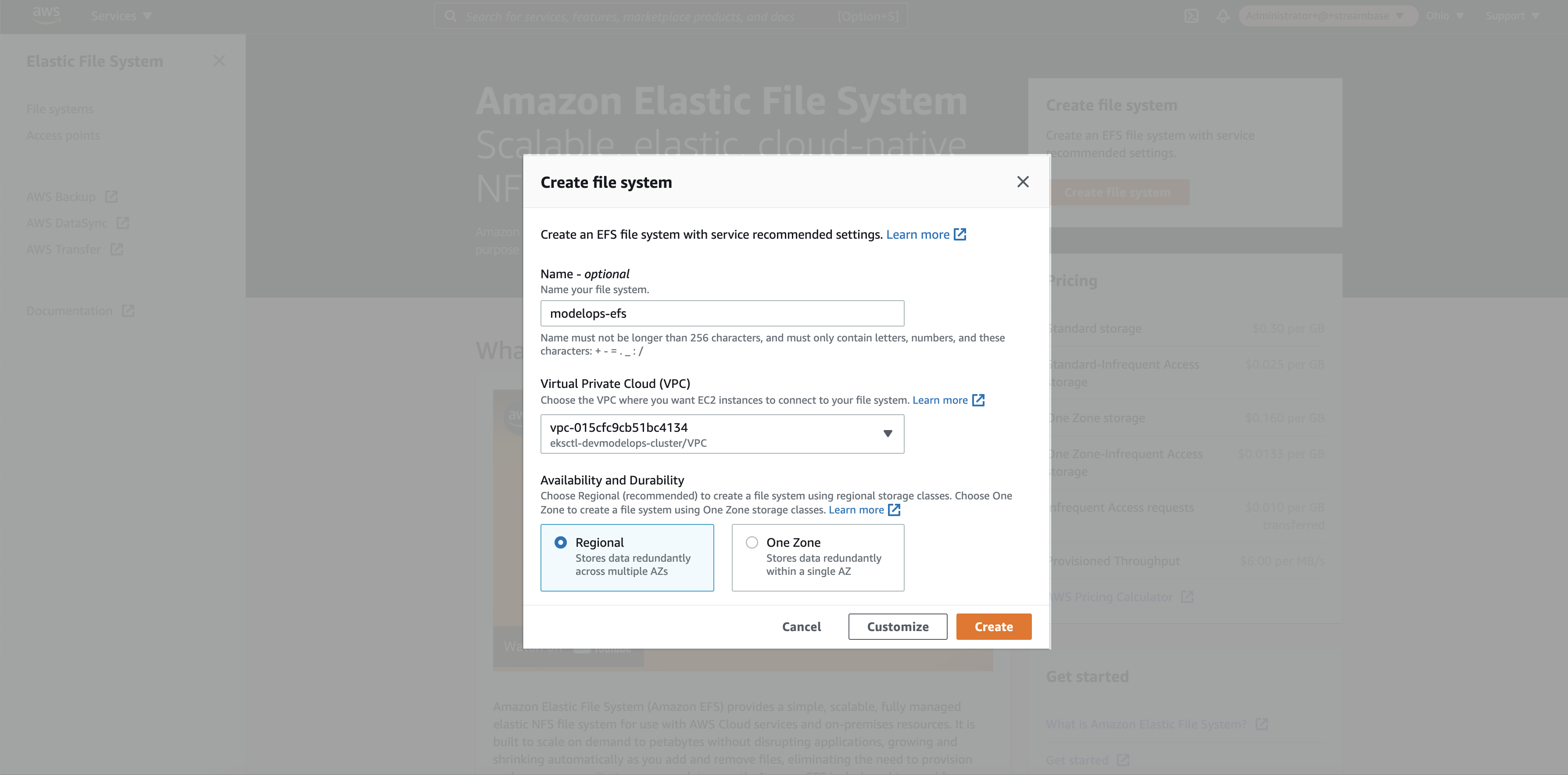
Note: VPC group should be the same for EFS and EKS cluster.
Step 3: Select the newly created EFS storage
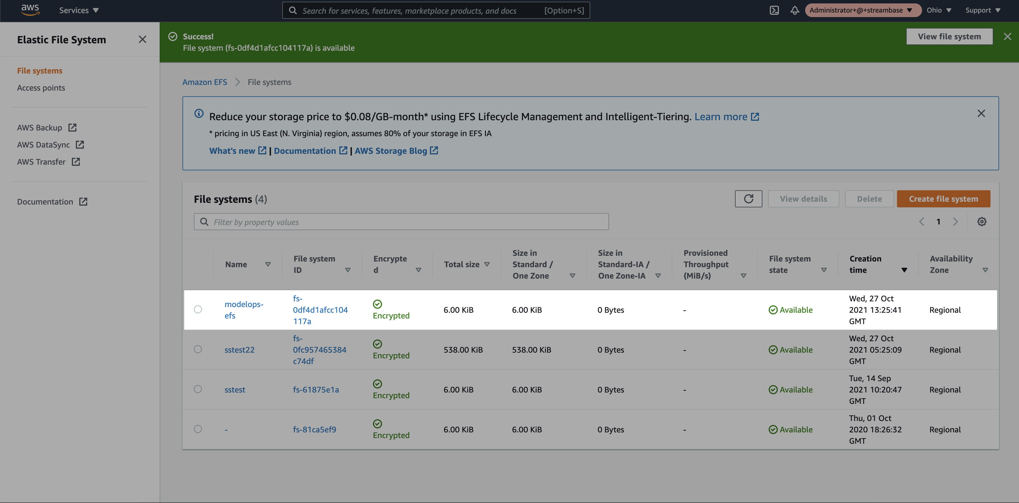
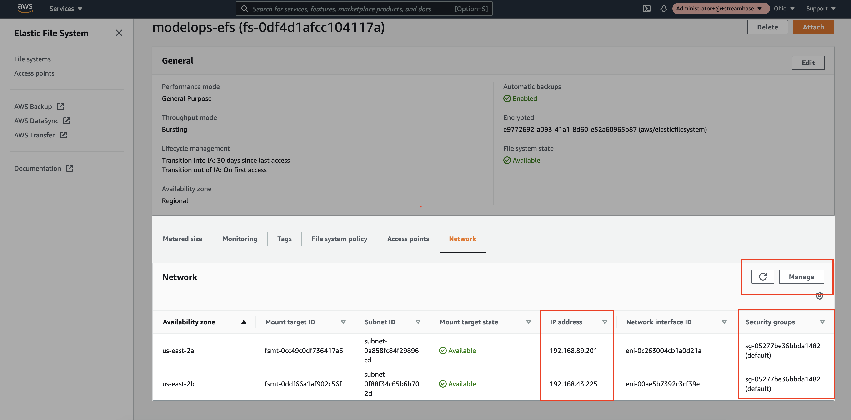
Step 4: Once the Elastic File system is in available state, in the network tab a new IP address will be assigned per Availability Zone. Select the same Security Group assigned to the EKS cluster
2. Create SFTP Server
AWS has provided a service called “AWS Transfer Family”. Using "AWS Transfer Family service, we can set up a SFTP server. The File Transfer Protocol is a standard communication protocol used for the transfer of computer files from a client to a server on a computer network. FTP is built on a client–server model architecture using separate control and data connections between the client and the server.
To configure the SFTP server, follow the simple steps :
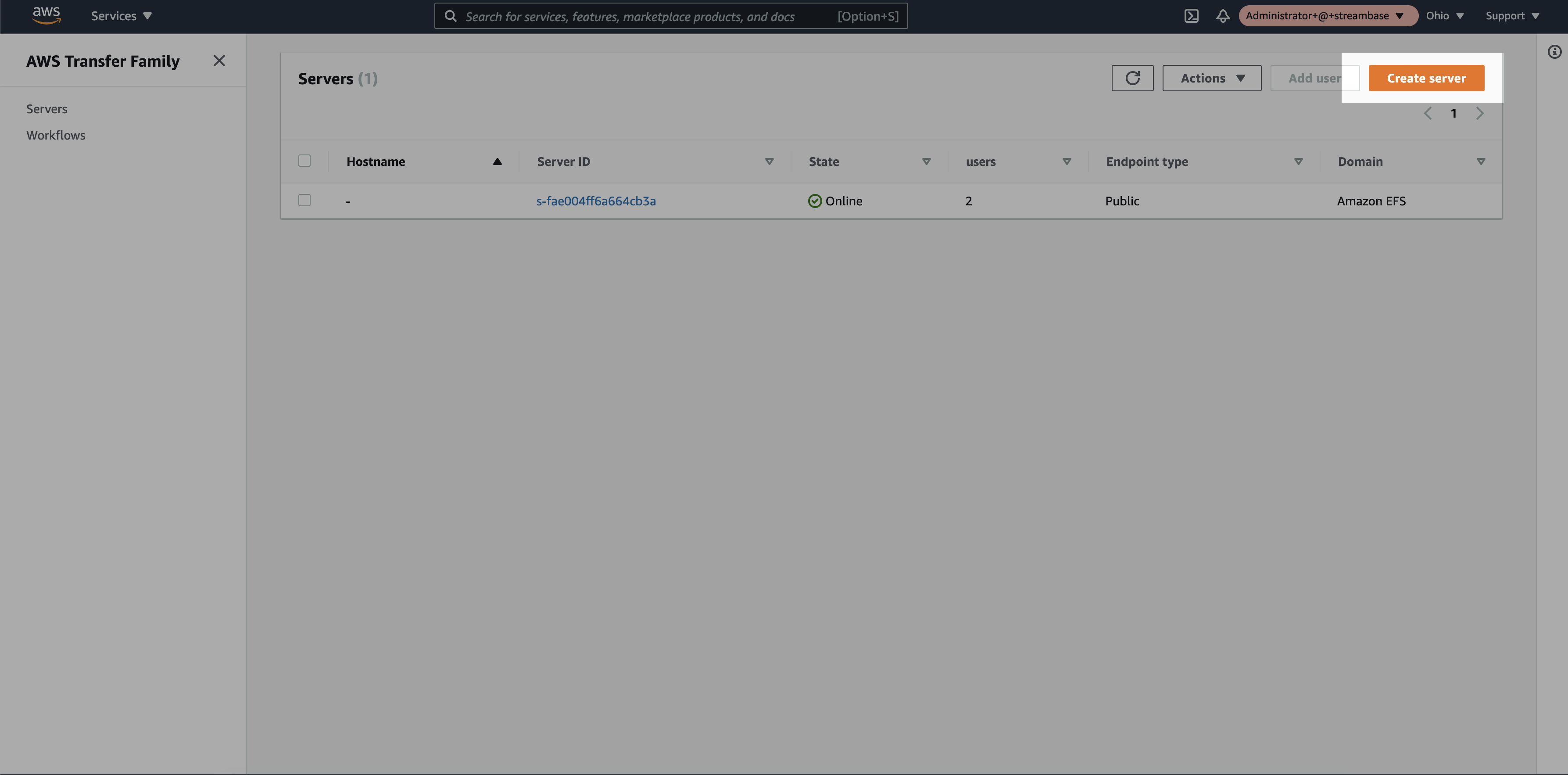
Step 1: Login to the AWS console and search for the “AWS Transfer Family” service. Click on “Create Server”
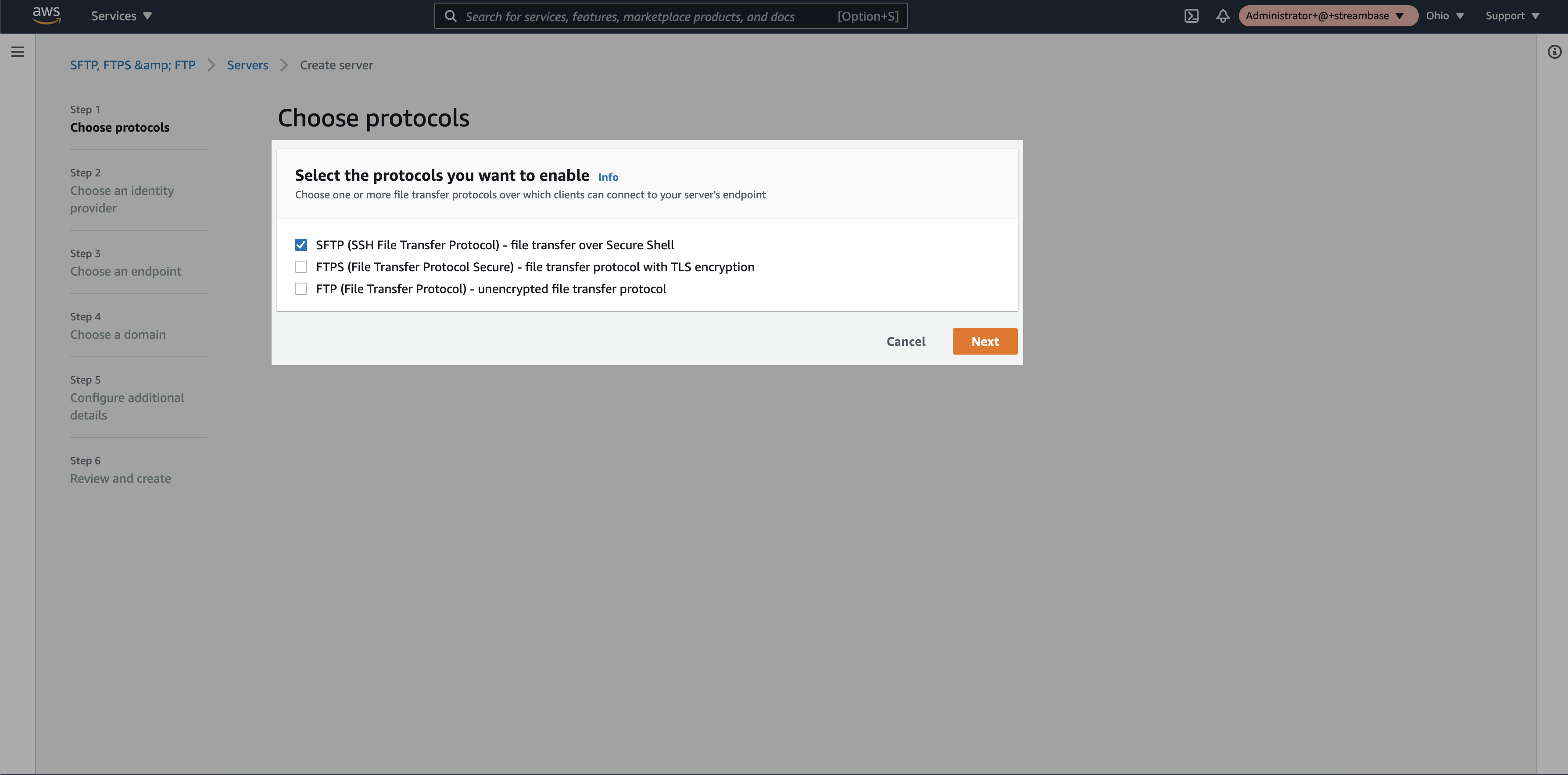
Step 2: Select “SFTP” option and click on “next”
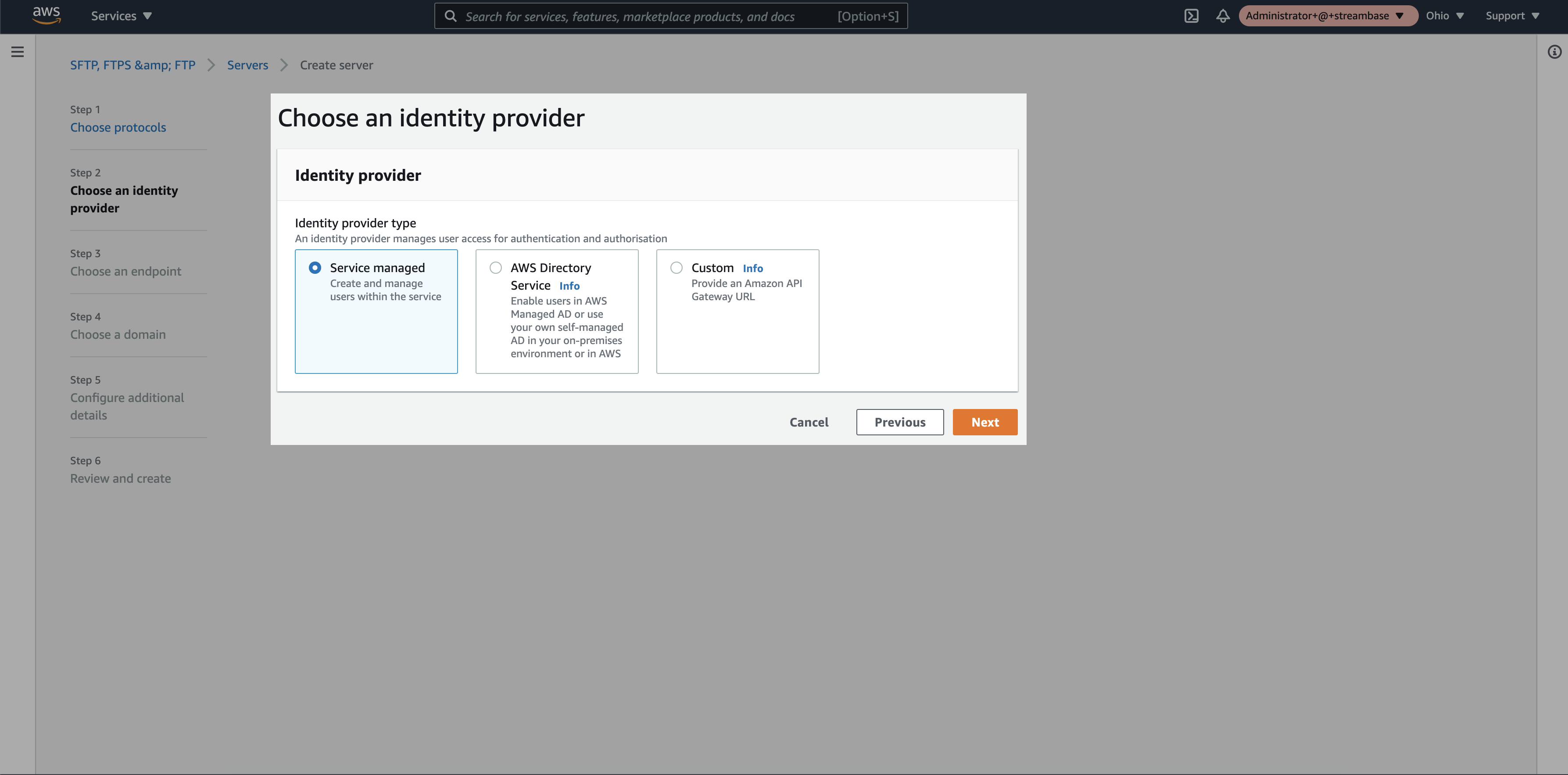
Step 3: Select identity provider as “Service Managed” and click on “next”
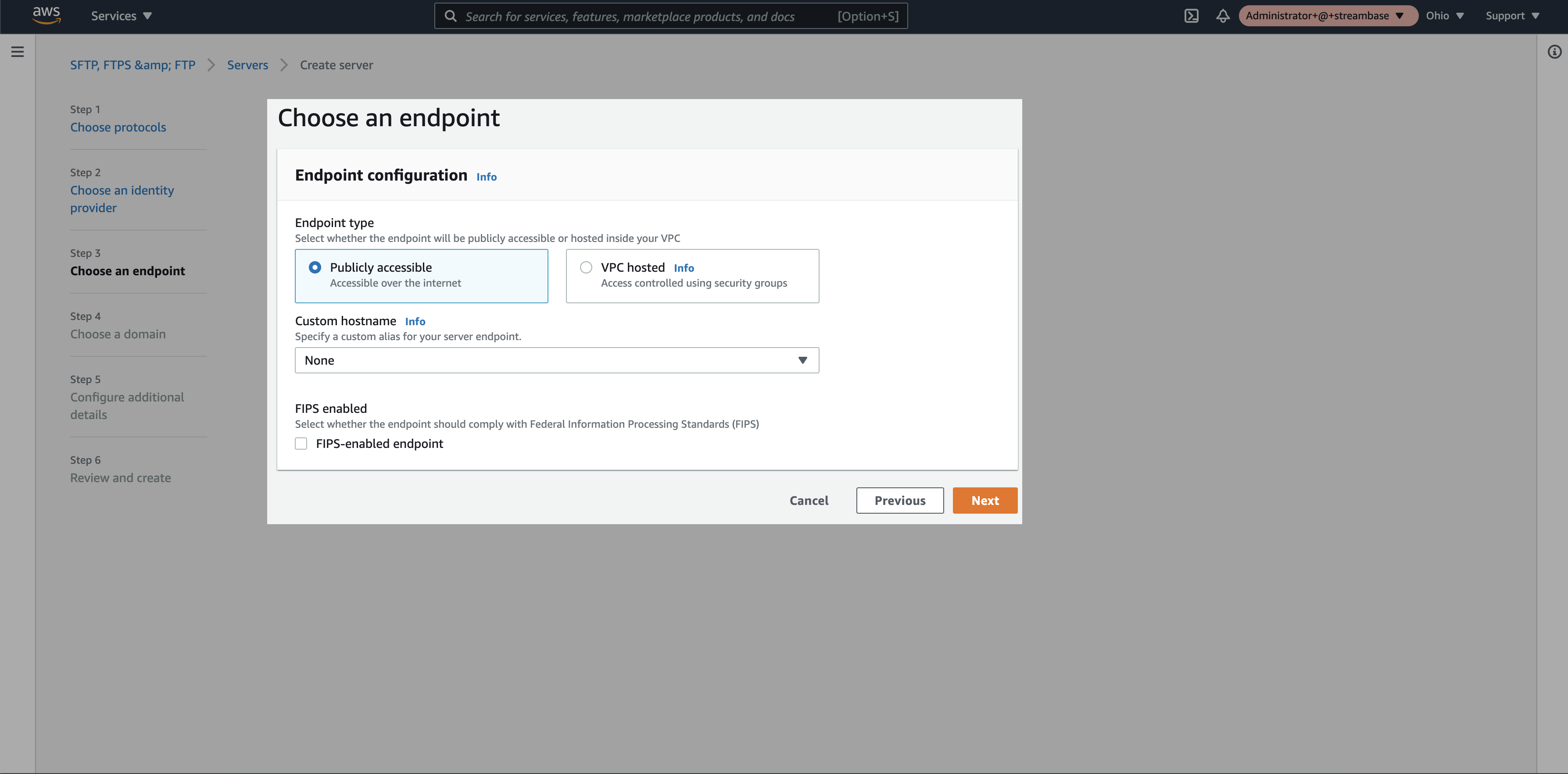
Step 4: Select “Publicly accessible” endpoint and click on “next”
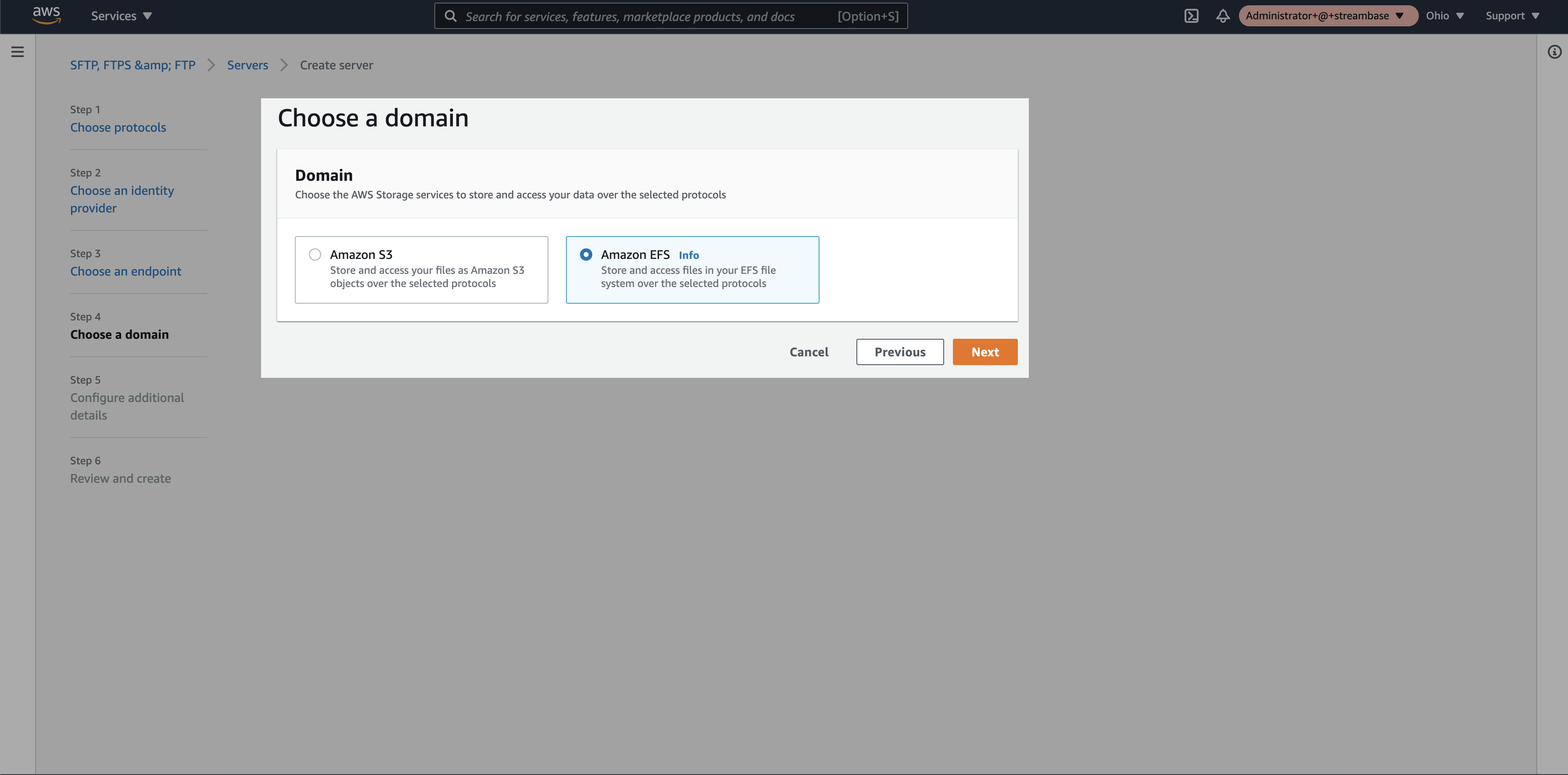
Step 5: Select “Amazon EFS” as a domain and click on “next”
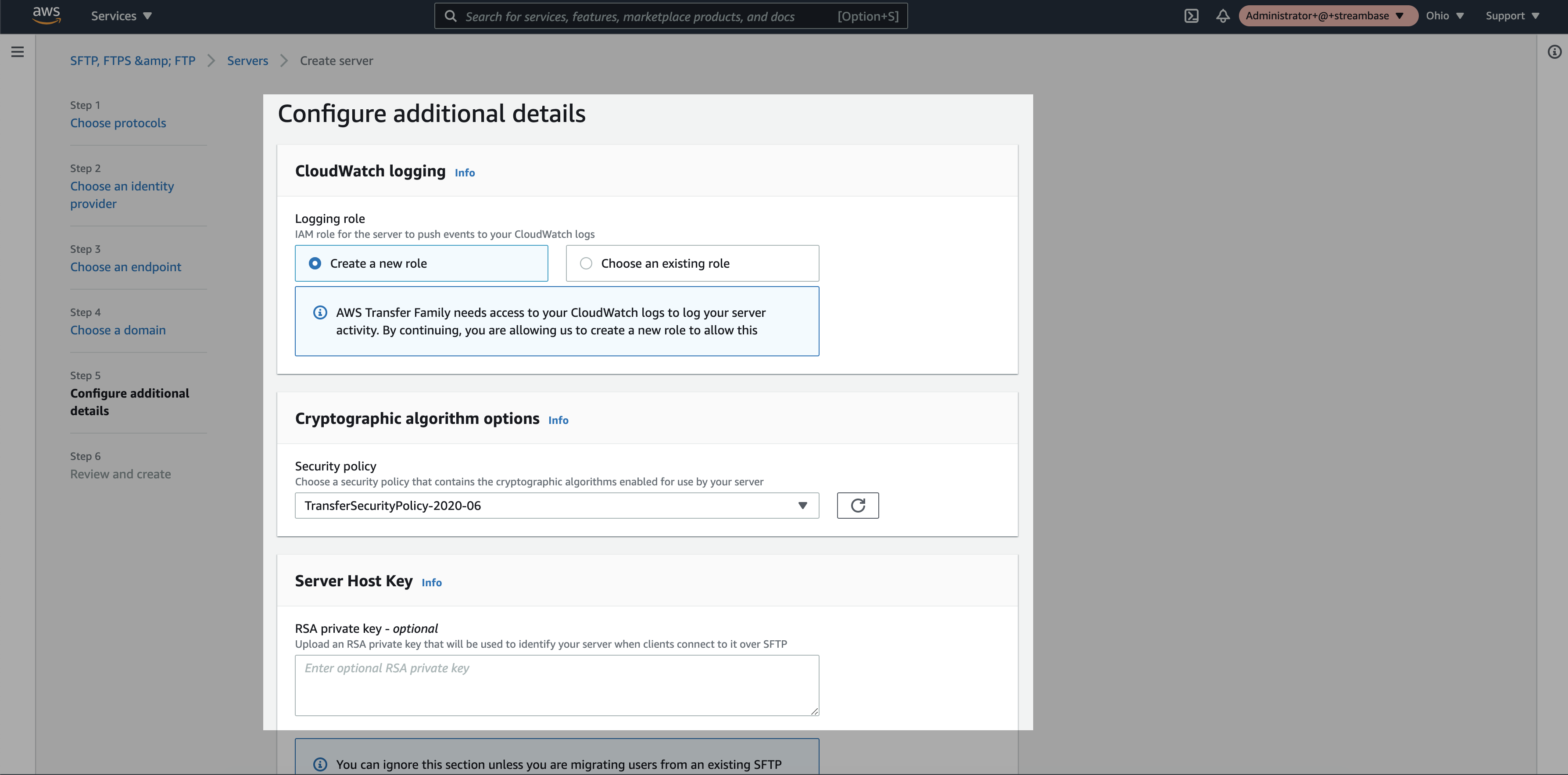
Step 6: Keep the default additional details and click on “next”
Step 7: Review the details and click on create
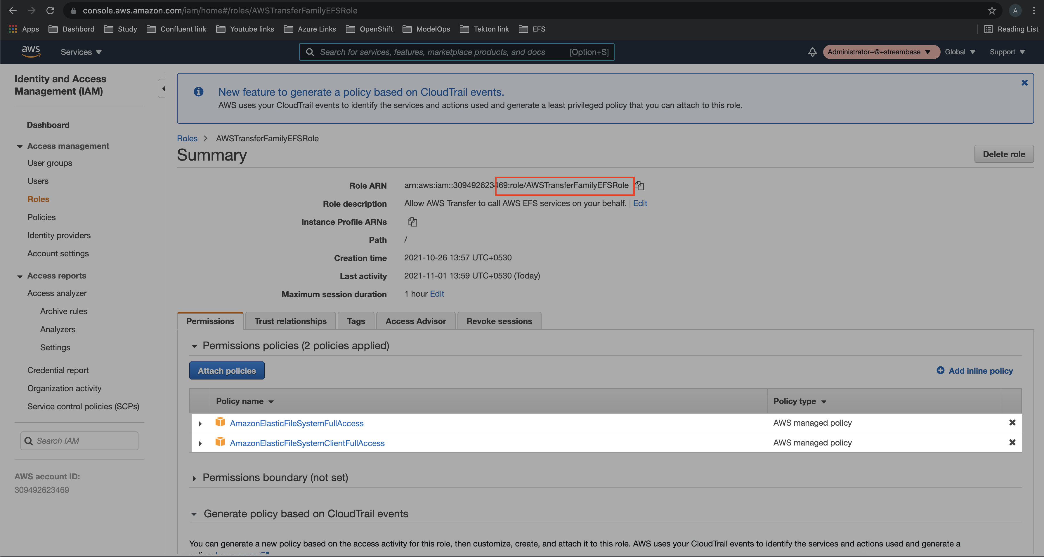
Step 8: Now, create a Role with below two policies in IAM section
- AmazonElasticFileSystemFullAccess
- AmazonElasticFileSystemClientFullAccess
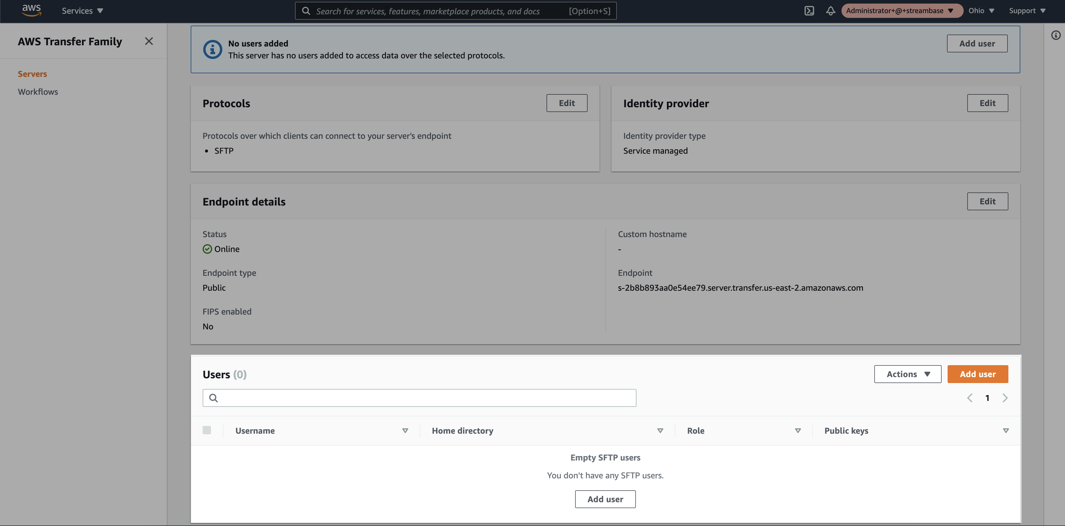
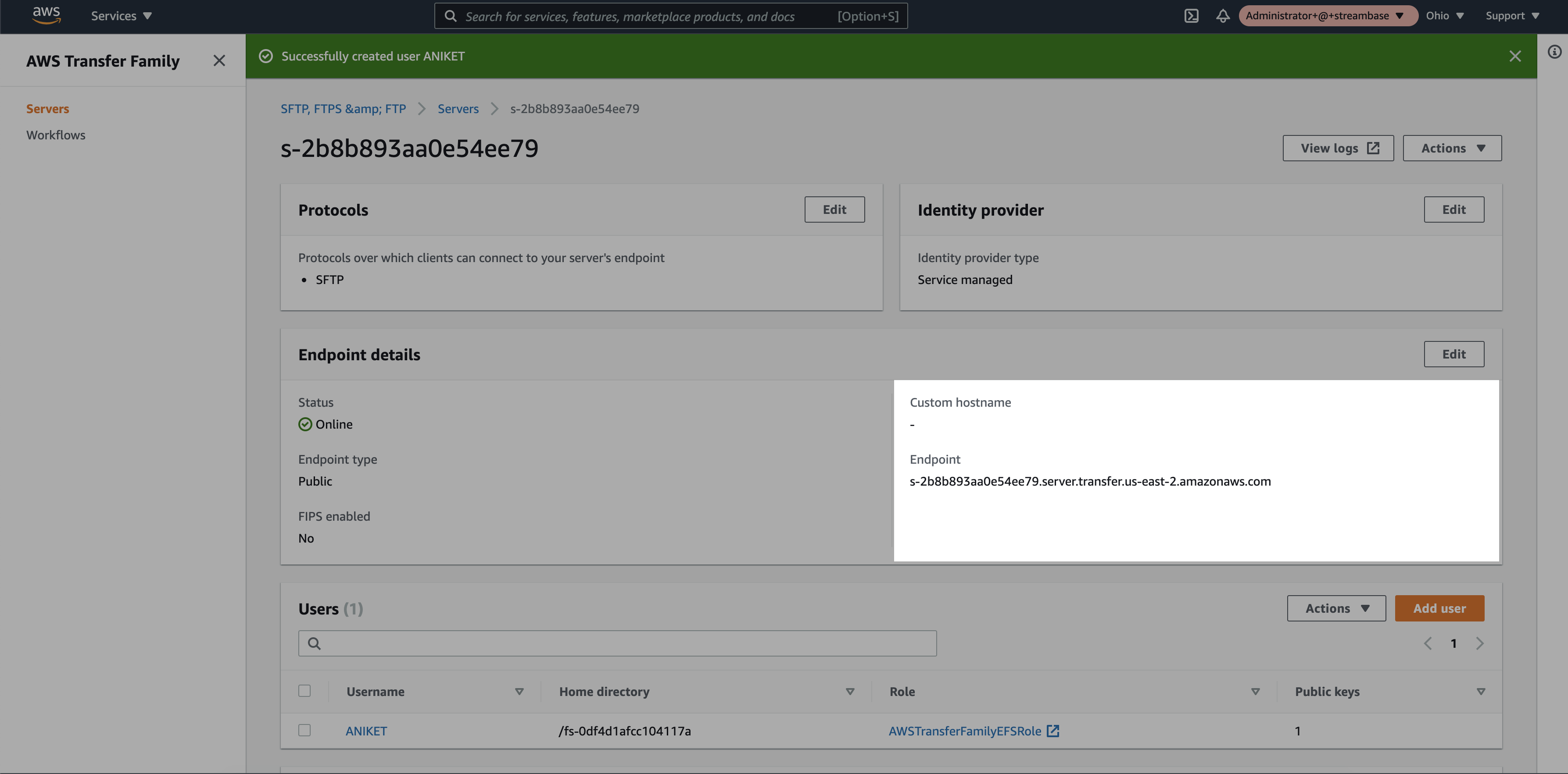
Step 9: Select the newly created SFTP server in AWS Transfer Family service
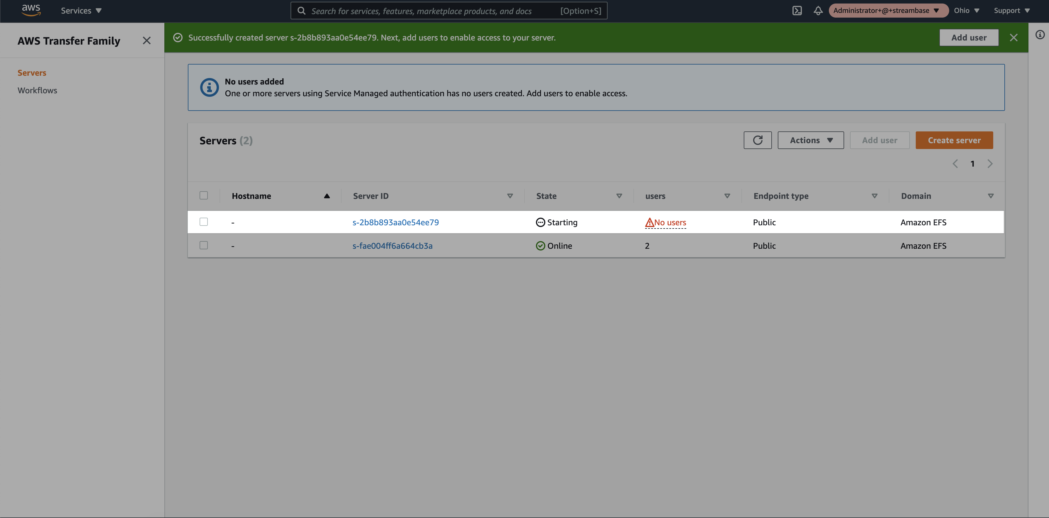
Step 10: Click on “Add User”
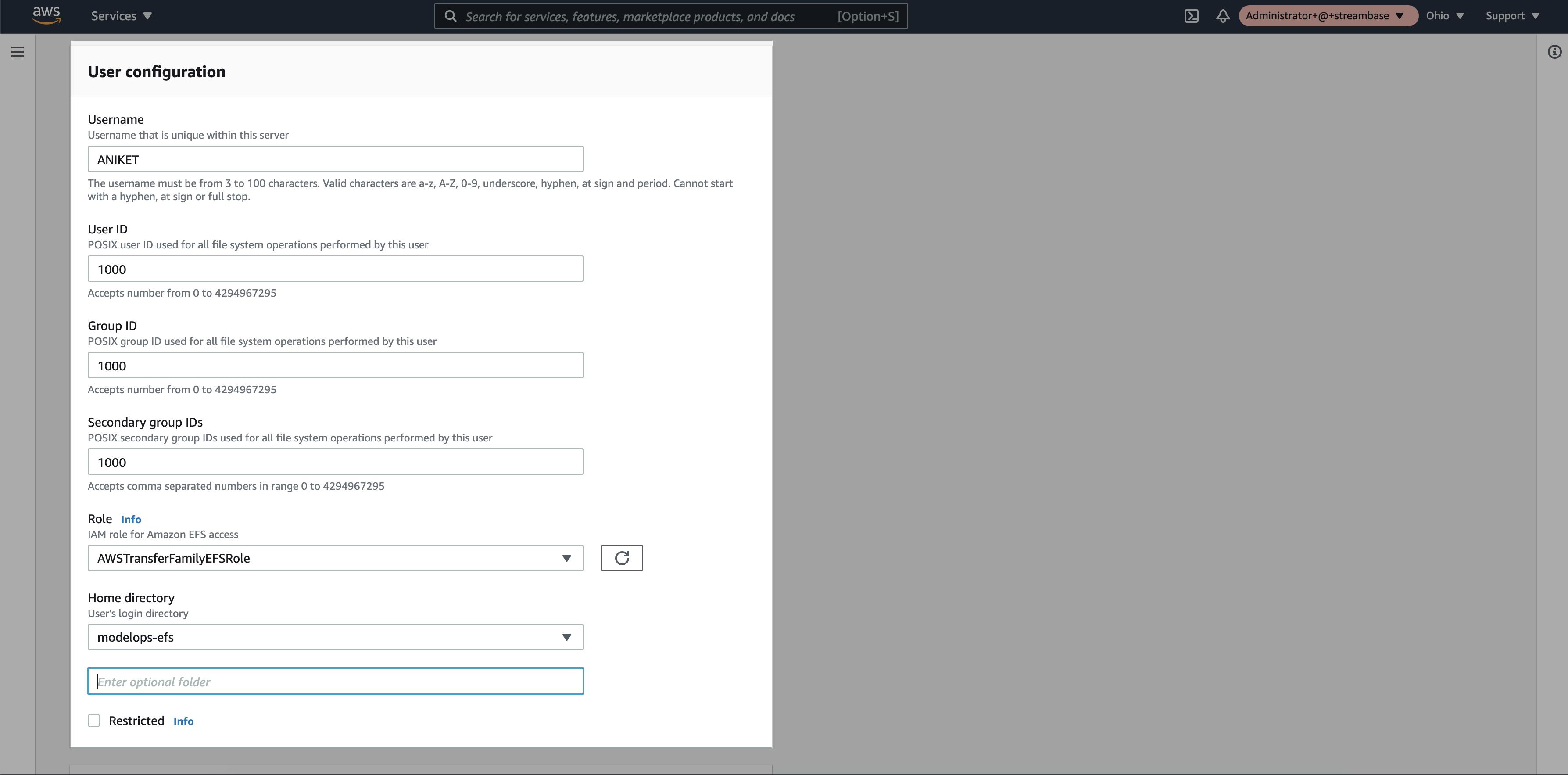
Step 11: Add the user details
- Username : Add username.
- User ID : It should be “1000”.
- Group ID : It should be “1000”.
- Secondary Group ID : It should be “1000”.
- Role : Select the newly created IAM Role.
- Home directory: Select the EFS storage name that we created in EFS step 2.
- SSH Public key: Generate “ssh-rsa” key on your machine and add public key here.
- Windows Key generation. (https://docs.microsoft.com/en-us/windows-server/administration/openssh/openssh_keymanagement#user-key-generation)
- MacOS/Linux Key generation. (https://docs.rightscale.com/faq/How_Do_I_Generate_My_Own_SSH_Key_Pair.html)
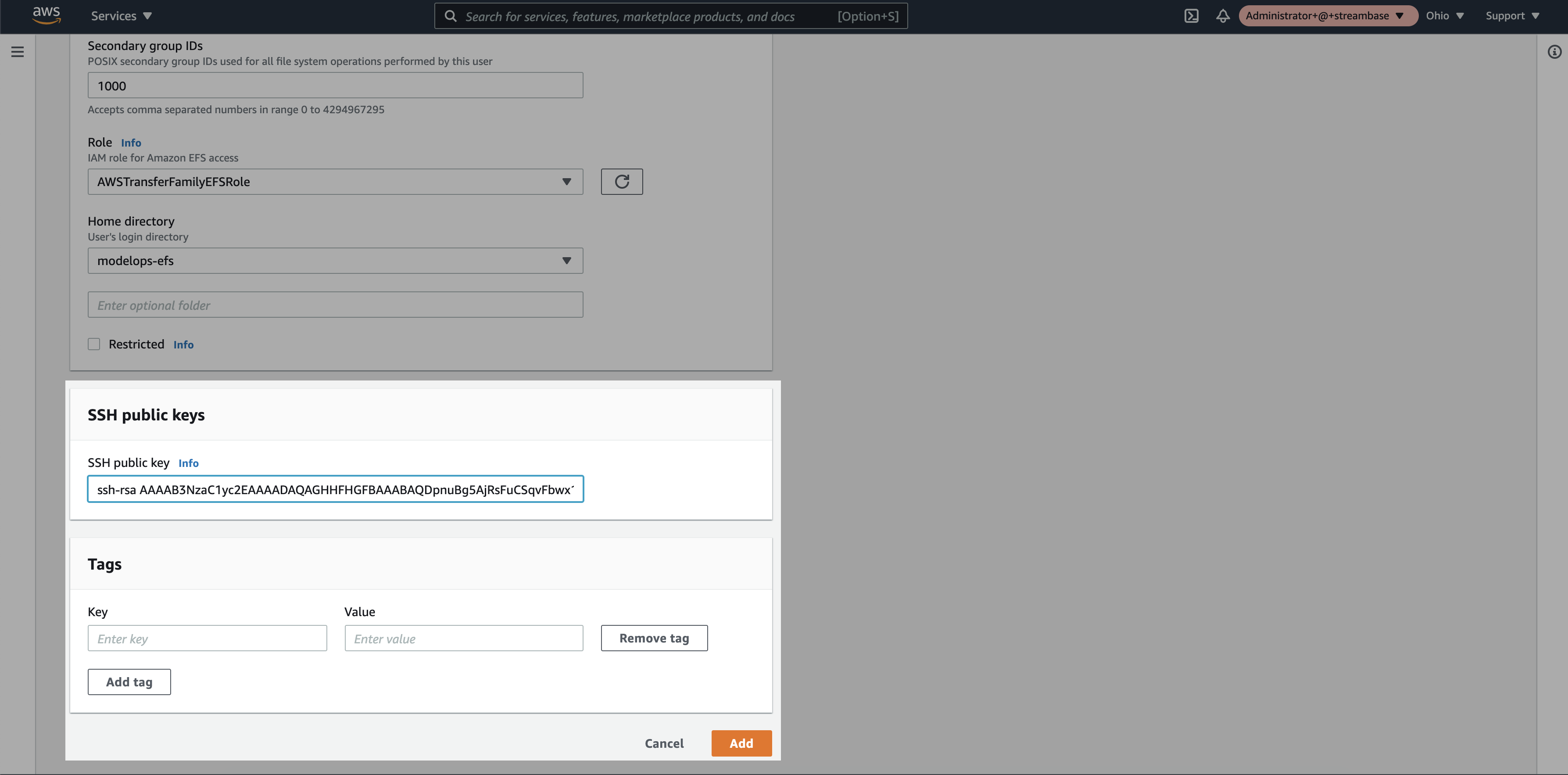
Step 12: Click on “Add”
Step 13: Click on the SFTP server and note the endpoint and username
Note: Copied endpoint will be used as a hostname in SFTP client tool configuration.
3. SFTP Client Tool Setup
Follow the simple steps for SFTP Client tool configuration:
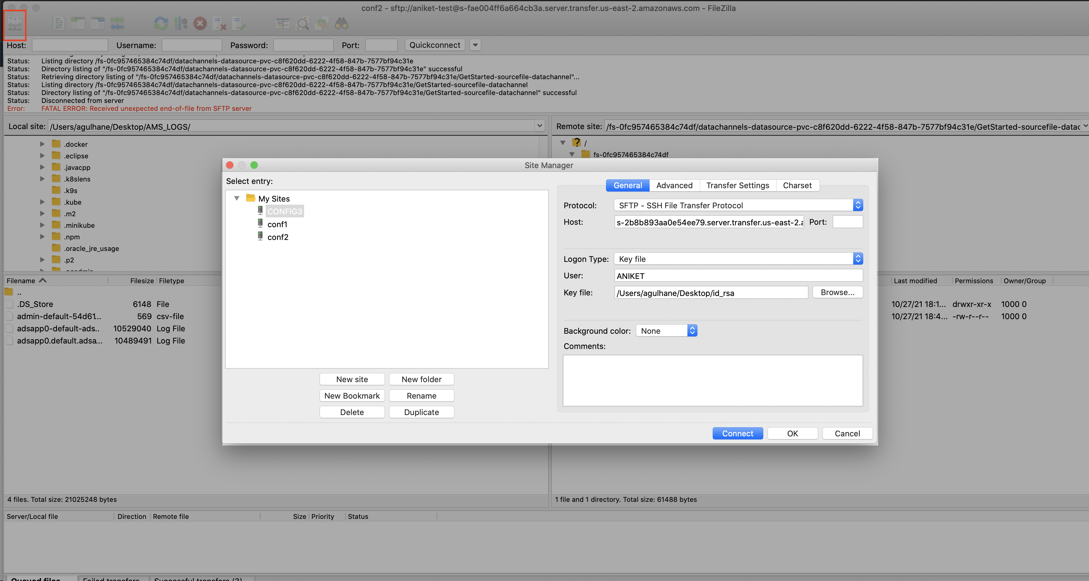
Step 1. SFTP Configuration
- Download and install one of the SFTP client tools (WinSCP or FileZilla).
- Click on the “Site manager”.
- Click on “New Site” and provide a suitable name.
- Select protocol “SFTP”.
- Copy the endpoint from SFTP server and paste it under “Host”.
- Select Logon type “SSH key file”.
- Provide username created at SFTP server.
- Add SSH private key.
- Click on connect
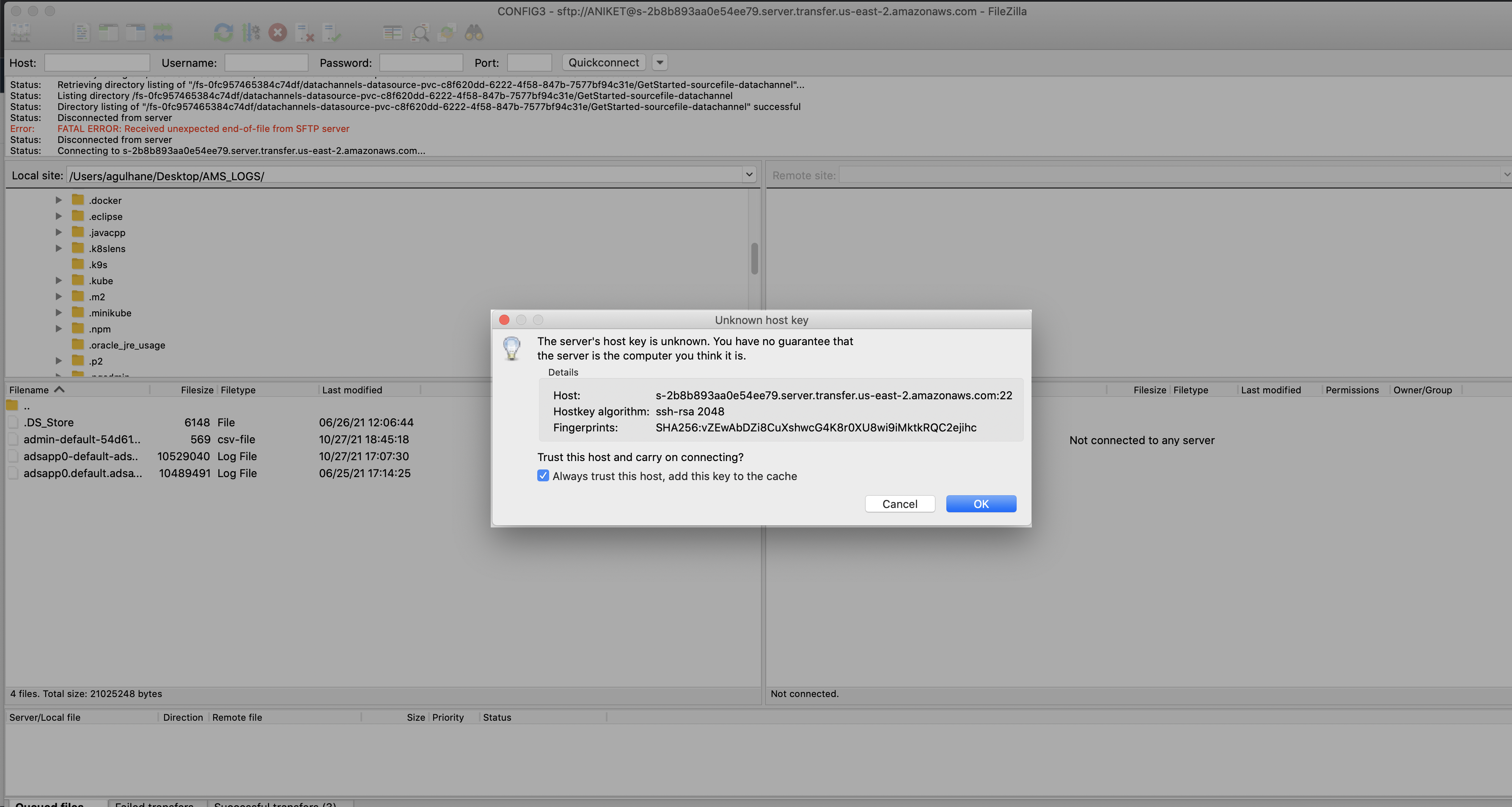
Step 2. Accept the host key for the first time
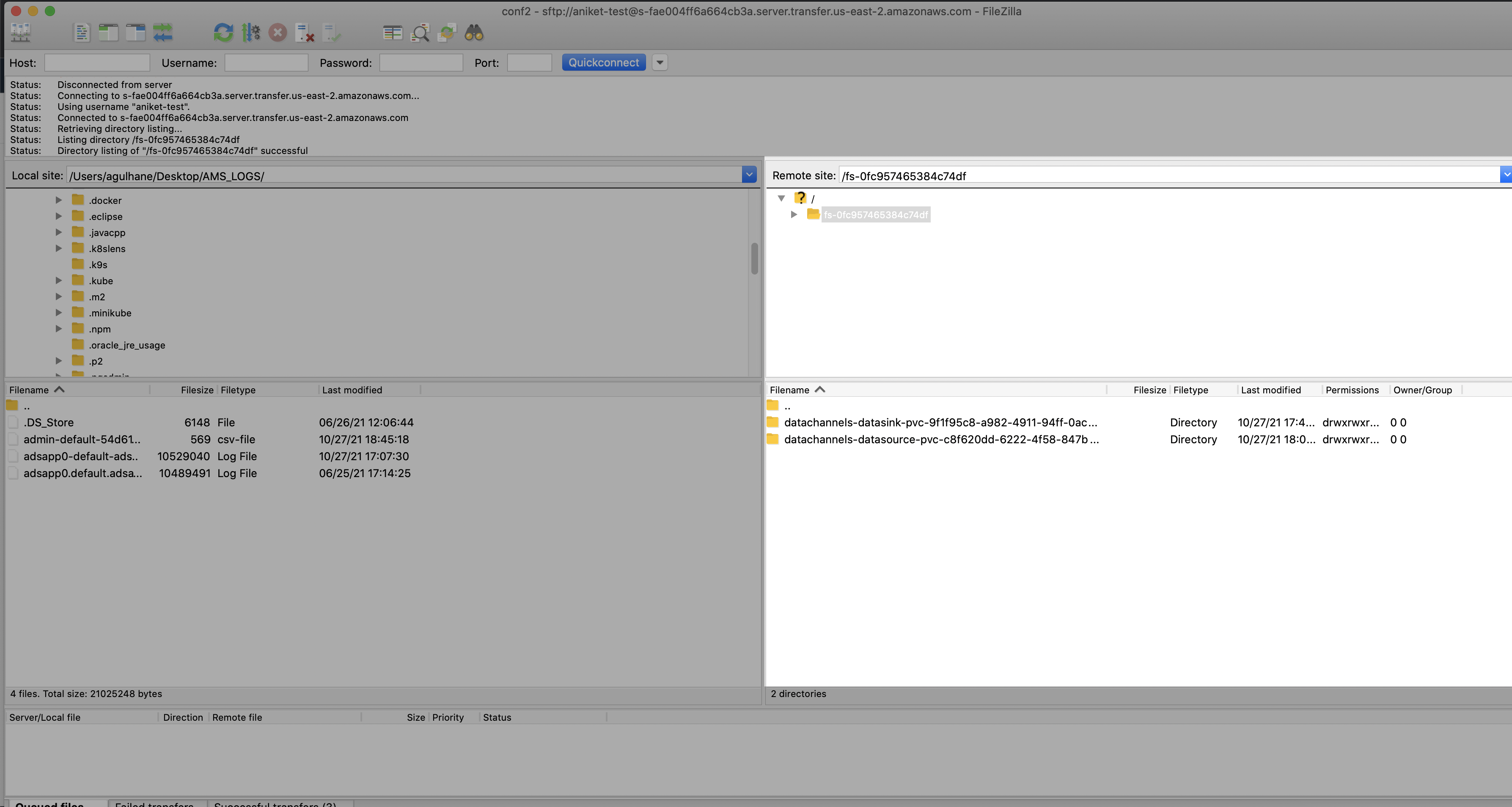
Step 3. Once the file channel setup is done then the user can see the file-datasource folder as below
4. EFS Configuration at EKS cluster
Configure the EFS storage in EKS cluster.
Follow below steps for configuration:
Step 1: Create a new namespace for hosting the provisioner
Namespace.yaml
	apiVersion: v1
	kind: Namespace
	metadata:
	name: <namespace name>
To apply the above changes, execute below command:
kubectl apply -f Namespace.yaml
Step 2: Create a service account
Service account is used to for deployment of provisioner
Service-Account.yaml
 	apiVersion: v1
	kind: ServiceAccount
	metadata:
  	  name: nfs-client-provisioner
  	  namespace: <namespace name>
To apply the above changes, execute below command:
kubectl apply -f Service-Account.yaml
Step 3: Create a cluster roles
Using this step it grants permission to entire cluster, and provisioner can create those objects
Cluster-Role.yaml
  kind: ClusterRole
  apiVersion: rbac.authorization.k8s.io/v1
  metadata:
    name: nfs-client-provisioner-runner
  rules:
    - apiGroups: [""]
      resources: ["nodes"]
      verbs: ["get", "list", "watch"]
    - apiGroups: [""]
      resources: ["persistentvolumes"]
      verbs: ["get", "list", "watch", "create", "delete"]
    - apiGroups: [""]
      resources: ["persistentvolumeclaims"]
      verbs: ["get", "list", "watch", "update"]
    - apiGroups: ["storage.k8s.io"]
      resources: ["storageclasses"]
      verbs: ["get", "list", "watch"]
    - apiGroups: [""]
      resources: ["events"]
      verbs: ["create", "update", "patch"]
To apply the above changes, execute below command:
kubectl apply -f Cluster-Role.yaml
Step 4: Bind the cluster roles to the service account
This step binds the service account with the cluster role
Cluster-RoleBinding.yaml
  kind: ClusterRoleBinding
  apiVersion: rbac.authorization.k8s.io/v1
  metadata:
    name: run-nfs-client-provisioner
  subjects:
    - kind: ServiceAccount
      name: nfs-client-provisioner
      namespace: <namespace name>
  roleRef:
    kind: ClusterRole
    name: nfs-client-provisioner-runner
    apiGroup: rbac.authorization.k8s.io
To apply the above changes, execute below command:
kubectl apply -f Cluster-RoleBinding.yaml
Step 5: Create roles
Role.yaml
  kind: Role
  apiVersion: rbac.authorization.k8s.io/v1
  metadata:
    name: leader-locking-nfs-client-provisioner
    namespace: <namespace name>
  rules:
    - apiGroups: [""]
      resources: ["endpoints"]
      verbs: ["get", "list", "watch", "create", "update", "patch"]
To apply the above changes, execute below command:
kubectl apply -f Role.yaml
Step 6: Create role binding
Role-Binding.yaml
  kind: RoleBinding
  apiVersion: rbac.authorization.k8s.io/v1
  metadata:
    name: leader-locking-nfs-client-provisioner
    namespace: <namespace name>
  roleRef:
    kind: Role
    name: leader-locking-nfs-client-provisioner
    apiGroup: rbac.authorization.k8s.io
  subjects:
  - kind: ServiceAccount
    name: nfs-client-provisioner
    #replace with namespace where provisioner is deployed
    apiGroup: rbac.authorization.k8s.io
    namespace: <namespace name>
To apply the above changes, execute below command:
kubectl apply -f Role-Binding.yaml
Step 7: Create a EFS provisioner Note: In the below request pass the IP address or DNS name of the EFS server. Refere the screenshot from step 4 of Create EFS Storage
Provisioner.yaml
  kind: Deployment
  apiVersion: apps/v1
  metadata:
    name: nfs-client-provisioner
    namespace: <namespace name>
  spec:
    replicas: 1
    strategy:
      type: Recreate
    selector:
      matchLabels:
        app: nfs-client-provisioner
    template:
      metadata:
        labels:
          app: nfs-client-provisioner
      spec:
        serviceAccountName: nfs-client-provisioner
        containers:
          - name: nfs-client-provisioner
            image: k8s.gcr.io/sig-storage/nfs-subdir-external-provisioner:v4.0.2
            volumeMounts:
              - name: nfs-client-root
                mountPath: /persistentvolumes
            env:
              - name: PROVISIONER_NAME
                value: nfs-storage  # Need to pass this value in next step
              - name: NFS_SERVER
                value: 172.31.27.152 # Pass the NFS IP address
              - name: NFS_PATH
               value: /
        volumes:
          - name: nfs-client-root
            nfs:
              server: 172.31.27.152 # Pass the NFS IP address
              path: /
To apply the above changes, execute below command:
kubectl apply -f Provisioner.yaml
Step 8: Create Storage class which will be used for creating PVCs Pass the provisioner name that was created in Step-7
Storage-class.yaml
  apiVersion: storage.k8s.io/v1
  kind: StorageClass
  metadata:
    name: managed-nfs-storage
  provisioner: nfs-storage # Created in step 7
  parameters:
    archiveOnDelete: "false"
To apply the above changes, execute below command:
kubectl apply -f Storage-class.yaml
Step 9: Create PVC for DataSource and Sink
We don’t need to create PV as it gets dynamically provisioned.
PVC.yaml
  apiVersion: v1
  kind: PersistentVolumeClaim
  metadata:
    name: datasource
    namespace: datachannels
  spec:
    storageClassName: managed-nfs-storage
    accessModes:
    - ReadWriteMany
    resources:
      requests:
        storage: 10Mi
To apply the above changes, execute below command:
kubectl apply -f PVC.yaml
JDBC Channels
This section provides:
- Information on how to use a JDBC driver with JDBC data channels.
- Some useful links and tips for installing and running a TIBCO® Data Virtualization (TDV) server with TIBCO® ModelOps.
JDBC Driver installation
JDBC data channels can automatically download and install JDBC drivers hosted in Maven central repository. If a JDBC driver is not hosted in the Maven central repository, it must be manually installed into the ModelOps Maven artifact repository.
JDBC data channels support configuration of specific JDBC drivers hosted in Maven central and ModelOps Maven arifact repositories. The required maven artifact coordinates must be configured when authoring the JDBC data channels. JDBC data channel configuration options are explained in detail here.
TIBCO® Data Virtualization (TDV) JDBC driver
TDV JDBC drivers are not available in the Maven central repository, and must be manually installed.
-
TDV JDBC driver ( csjdbc.jar ), available with TIBCO Data Virtualization (TDV) 8.4 or 8.5 server installation must be uploaded to the TIBCO® ModelOps maven artifact repository.
- This JAR file is available within the TDV installation directory.
<TDV_installation_directory>\apps\jdbc\libTDV_installation_directory is just a placeholder to the actual TDV installation directory path.
- This JAR file is available within the TDV installation directory.
-
The connecting to TDV server through JDBC page provides more information on installing and updating the TDV JDBC drivers for accessing the TDV server from client applications.
Manually Installing JDBC Drivers
TIBCO® ModelOps server uses the Nexus Repository as its internal maven artifact repository.
Port forwarding
The port forwarded network address of the TIBCO® ModelOps artifact-repository service can be used to access the Nexus Repository Manager’s artifact upload page on a web browser.
Before executing the steps below, confirm that:
- TIBCO® ModelOps Kubernetes cluster is up and running.
- Kubectl command-line tool is configured to communicate with the running ModelOps cluster.
- If required, set the current context to the desired cluster to access the intended pods.
Execute the commands in the following steps using the Kubectl command-line tool:
-
Get the full pod name of the running artifact-repository service.
kubectl get pods --namespace <namespace-name> | grep "artifact-repository"namespace-name is the desired namespace where the artifact-repository service is available. For example, modelops.
-
Get the artifact-repository service port.
kubectl get pod <artifact-repository-service-name> --template="{{(index (index .spec.containers 0).ports 0).containerPort}}" --namespace <namespace-name>artifact-repository-service-name is the full pod name of the running artifact repository service from step 1.
-
Forward a local port to the artifact repository service port.
kubectl port-forward <artifact-repository-service-name> <local-port>:<hosted-port> --namespace <namespace-name>local-port is any available local port to forward the artifact-repository service and hosted-port is the original artifact-repository service port on the running pod.
-
Open the Nexus Repository on a web browser.
localhost:<local-port>
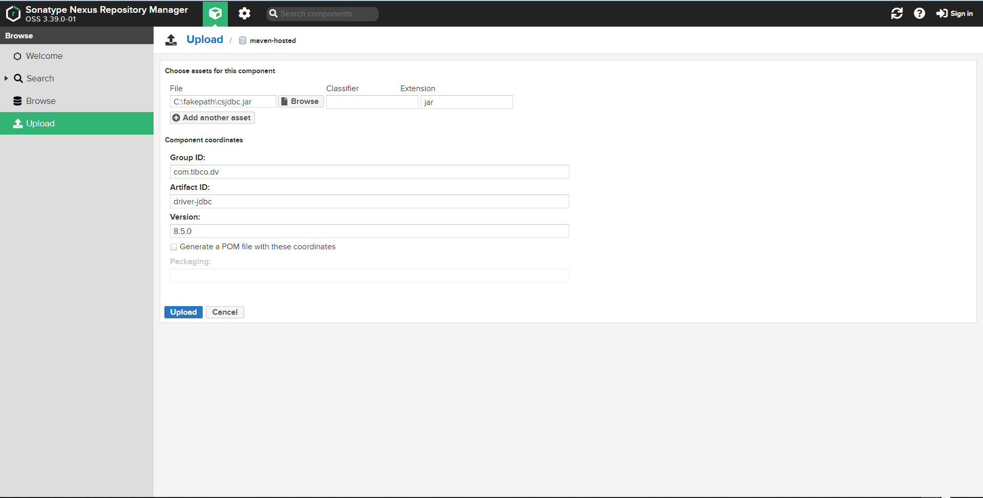
After opening the Nexus Repository in a web browser, TIBCO® ModelOps users can upload new maven artifacts to the maven-hosted repository from the Nexus Repository Manager page.
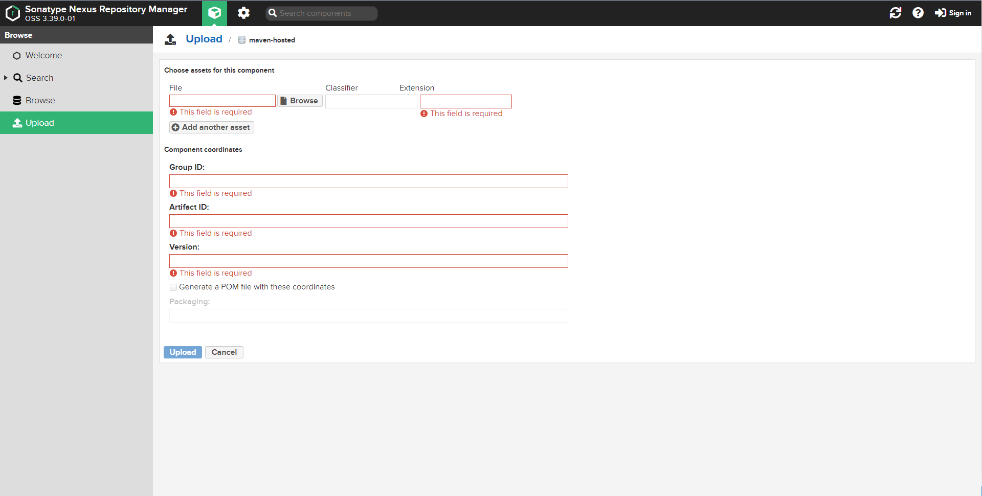
An example maven coordinates for hosting a TDV JDBC driver from the Nexus Repository Manager page is shown in the following screenshot.
To summarize:
- Access the ModelOps Maven repository using port forwarding.
- Note: If login credentials are set for the artifact repository then sign-in using the appropriate credentials.
- Upload the Maven artifact.
TIBCO® Data Virtualization (TDV) server on Azure Virtual Machines
TIBCO® ModelOps JDBC data channels can connect to TIBCO® Data Virtualization (TDV) servers that are installed on Azure Virtual Machines running on the same virtual network/subnet as the TIBCO® ModelOps server.
Required Software Components
TDV provides installers for several Data Virtualization software components as discussed here. The TDV Server is the only required component for connecting TIBCO® ModelOps JDBC data channels to TDV data sources.
Installation Guide
The TDV installation instructions for UNIX and Windows platforms are available at:
Web UI
For creating new TDV data sources or views, use the TDV Web UI. The TDV Web UI should be available at the URL shown below after installing and running a TDV server.
http://<server>:<port>/webui/login
When running the TDV Server locally, the TDV Web UI shall be available at:
http://localhost:9400/webui/login
The TDV Web UI User Guide provides more information on this.
Port Requirements
By default, a TDV server listens on port 9401 for JDBC/OBDC connections and this port should allow inbound traffic for JDBC connections.
A TDV Server allows inbound traffic on ports 9400-9403 . This port range when exposed supports for non SSL and SSL TDV http and client access.
Port 9407 should be exposed only when using the TDV server in a cluster configuration.
A complete description of the TDV ports is available here.
Connection URL
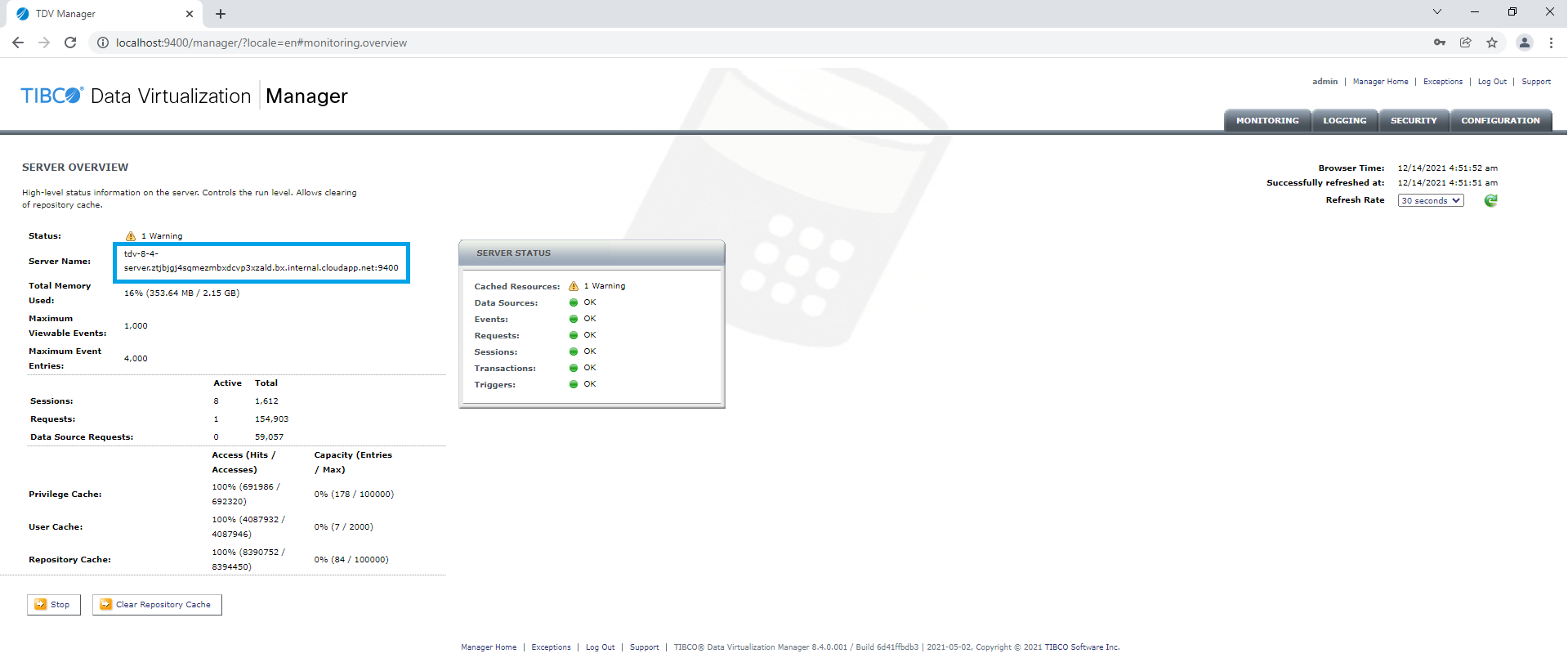
A TIBCO® Data Virtualization (TDV) connection URL contains a TDV server name, data source name and the JDBC port (default 9401).
After installing a TDV server, the server name can be obtained by running the TDV manager on port 9400.
The data source name can be obtained from the TDV manager Data Sources page.
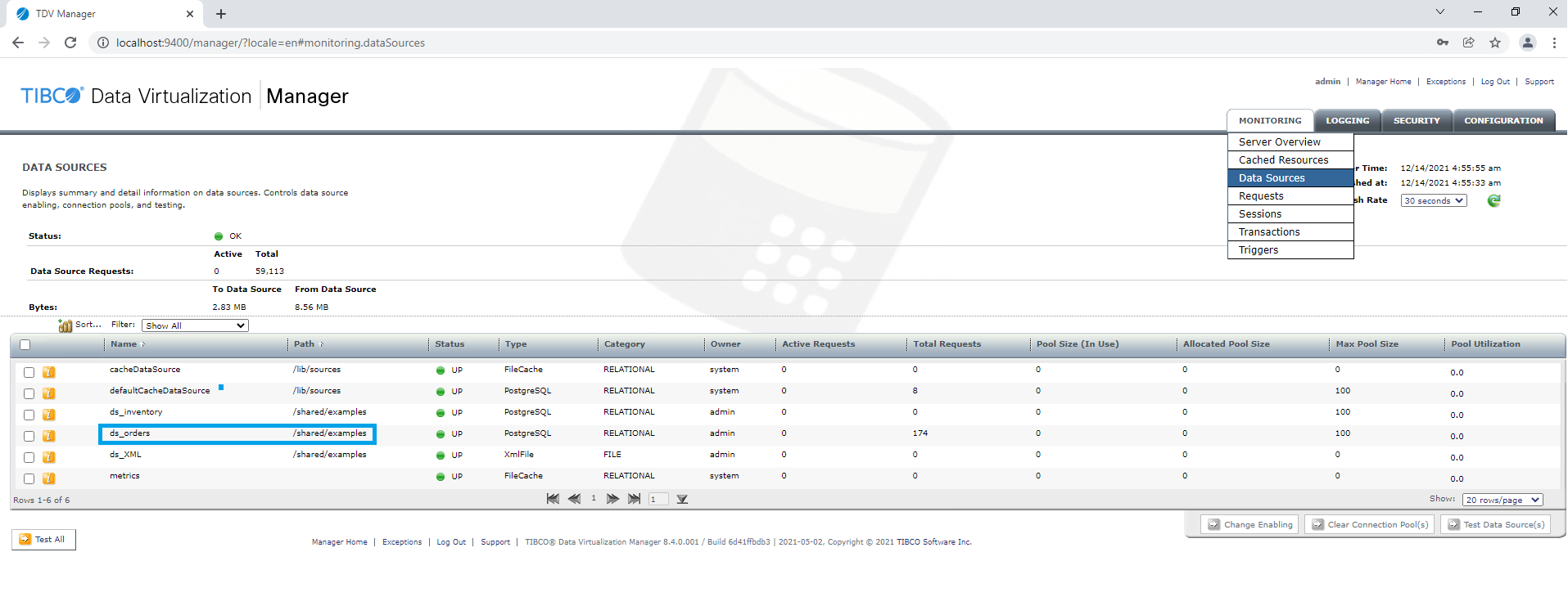
An example TDV connection URL is shown below:
jdbc:compositesw:dbapi@example.tibco.com:9401?domain=composite&dataSource=/shared/examples/ds_orders
TIBCO® Data Virtualization on Kubernetes
TIBCO Data Virtualization (TDV) is also supported in containerized environments as described here.
The TDV container must be running within the same ModelOps Kubernetes cluster as the JDBC data channels.
Required TIBCO® Data Virtualization (TDV) Work-Around
There is a known problem with the TDV JDBC driver (csjdbc.jar) available as part of TDV 8.4.x or 8.5.x installations that causes the TIBCO® ModelOps JDBC data channels to fail with a TDV data source connectivity error.
To resolve this problem, follow the steps provided below. Use the Java Archive Tool for the commands shown:
-
Unarchive the downloaded csjdbc.jar to a new empty directory.
jar -xvf <path-to-jdbc-driver-jar> -
Open the java.sql.Driver file in the ../META-INF/services directory using a text editor.
-
Fix the typo in the JDBC driver name:
Before the fix:
cs.jdbc.Driver.CompositeDriverAfter the fix:
cs.jdbc.driver.CompositeDriverNotice how the standalone word Driver between the dots was corrected to driver with a small ‘d’.
-
Archive the new directory contents to a JAR file.
jar cvf <jdbc-driver-jar-name> * -
Install the updated JAR file using the steps in, Manually Installing JDBC Drivers.