This article provides a high-level overview of the administration architecture and capabilities available to manage StreamBase applications.
StreamBase Applications in Depth described the general structure of applications. In that article applications and fragments were introduced and how they are deployed on nodes in a cluster. This article provides more details on the deployment and administration models.
The following concepts are used to describe the deployment architecture:
-
Machine — an execution context for a node.
-
Application — business specific functionality.
-
Fragment — an executable part of an application.
-
Cluster — a logical grouping of nodes that communicate to support an application.
-
Node — a container for engines.
-
Engine — executable context for a fragment.
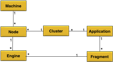
An application is executed on one or more clusters.
An application contains one or more fragments.
A fragment is executed on one or more engines.
A cluster can host a single application.
A cluster can contain one or more nodes.
A node can belong to one cluster.
A node can host one or more engines.
A machine can host one or more nodes.
The concepts described in Conceptual Model are mapped to physical entities as follows:
-
Machine — a physical or virtual computer.
-
Application — an application archive containing one or more fragments generated at design time as described in Design Time.
-
Fragment — a fragment archive containing executable application code generated at design time as described in Design Time.
-
Cluster — a collection of nodes interconnected by a network.
-
Node — a set of operating system processes running on a machine and monitored and managed by a node coordinator process.
-
Engine — an operating system process executing a fragment that is managed by the node coordinator.
Figure 4, “Deploying an application” shows a diagram of all of the physical entities.
All nodes are uniquely identified by a service name. A service name consists of these parts:
-
Cluster name
-
Optional grouping
-
Node name
Cluster, group, and node names are labels. The valid characters for a label are letters, numbers, and the hyphen character. No other punctuation is permitted. Labels must use the UTF-8 character set encoding.
A fully qualified service name consists of at least two labels separated by a period. A fully qualified service name includes the cluster name, the node name, and all grouping labels.
A partially qualified service name consists of at least one label, the cluster name, with a leading period. A partially qualified service name does not include the node name, and optionally only a subset of any grouping labels. A single label without a leading period is a special case and is treated as a cluster name.
Service names are arranged in a hierarchical tree structure, where the cluster name is the root of the tree and a node name is the leaf. The optional grouping part of a service name are the branches between a cluster name and a node name. More formally, the syntax is:
servicename = [nodename-label.[[group-label.]*]]clustername-label
Here are some example service names:
a.applicationcluster
b.eastcoast.applicationcluster
c.eastcoast.applicationcluster
d.westcoast.applicationcluster
e.westcoast.applicationcluster
These service names uniquely identify five different nodes, all in the same cluster.
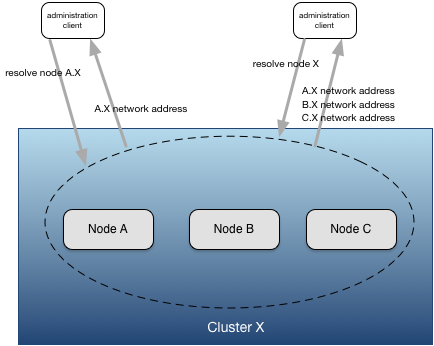
Services names are used by the discovery service (see Discovery Service) to locate network address information. Discovery can be performed using a fully-qualified or a partially-qualified service name. Fully-qualified service names always identify a single node. Partially-qualified service names may resolve to one or more nodes. For example using the service names above:
applicationcluster // resolves to all five nodes - notice no leading "."
.applicationcluster // resolves to all five nodes
.eastcoast.applicationcluster // resolves to nodes b and c.
.westcoast.applicationcluster // resolves to nodes d and e.
a.applicationcluster // resolves to node a.applicationcluster.
The examples above show that service name grouping allows sets of nodes to be resolved using a partially qualified service name. This is useful for administrating multiple nodes together. For example:
-
Nodes in different geographical locations might be configured with different connectivity.
-
Nodes grouped together to provide different high-availability guarantees.
-
Nodes that host one type of functionality may require different configuration from other nodes.
-
Nodes hosting different clients might require different operational rules.
The discovery service allows details about a node to be discovered using a service name, instead of specific network address.
When a node is installed it is available for discovery by the discovery service. A node registers multiple service records. Each service record has a different service type. Each service type makes available a different set of service properties that can be discovered. The different service types and properties are used by both nodes and client tools to dynamically discover information needed to perform specific tasks. For example, the administration client tool uses service discovery to dynamically find the administration port of a node.
Note
TIBCO recommends that you use service names instead of network addresses when accessing nodes.
Service discovery uses the UDP protocol to provide its services. To enable service discovery to work across machines, the UDP protocol must be enabled in all network routers and switches between nodes using service discovery.
Each node starts a UDP listener on all interfaces on the machine on which the node is running. All nodes in a cluster must use the same UDP listener port to successfully use service discovery.
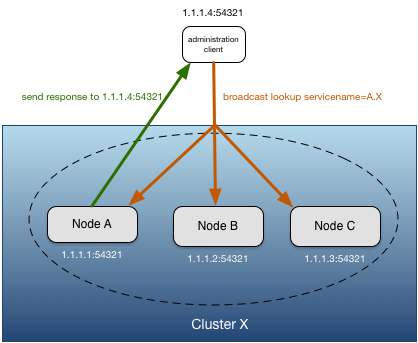
When a service discovery client, (for example, the administration tool), performs a service lookup, it sends a broadcast using the default broadcast port number, or a user specified port number. If the service discovery client is running on a multi-homed machine, the broadcast is sent on the interface that matches the local host name. Support is provided for explicitly specifying the interface(s) on which the broadcast should be sent. The client must send the broadcast on the same port number on which the nodes are listening for service discovery to resolve the nodes.
When a node receives a service discovery broadcast request, if the fully or partially qualified service name matches the node's service name, it sends a response directly back to the address that sent the request. Clients performing a service lookup may receive multiple responses to a single request for partially qualified service names and when multiple nodes are configured to provide proxy discovery services for the same node (see Proxy Discovery).
When a discovery client performs a service discovery lookup with a fully qualified service name, the discovery client completes the lookup when the first response is received, or no response is received after a configurable amount of time. When a lookup is performed with a partially qualified service name, a discovery client always waits a configurable amount of time for responses to the lookup.
As described in Network Architecture, service discovery relies on the underlying network supporting UDP broadcast. There are scenarios where this is not the case. Common examples are:
-
Nodes communicating over a WAN to provide disaster recovery.
-
Nodes deployed to cloud infrastructure.
To support service discovery in these environments proxy discovery can be used. Proxy discovery allows nodes that are not the requested service name to respond with the service properties for the requested service name. The network address information to return is configured in the node acting as the proxy. While multiple nodes can act as a proxy for the same service name, it is critical that all of the nodes have the same information configured to ensure that consistent results are returned for discovery requests.
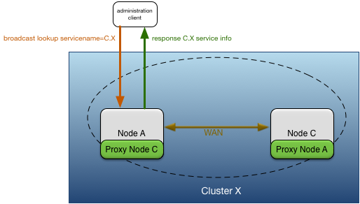
Figure 4, “Proxy discovery” shows node A providing proxy discovery services for node C because of the WAN connection between node A and C.
These service types are registered by nodes:
The table below summarizes service properties for each services type.
application service type properties
| Property Name | Property Description | Example |
|---|---|---|
| Service Name | Partially qualified application name. | MyApplication |
| Network Address | Not used. | |
| description | Application description. | My application |
| cluster | Cluster name. | X |
cluster service type properties
| Property Name | Property Description | Example |
|---|---|---|
| Service Name | Partially qualified service name for cluster. | X |
| Network Address | Not used. |
distribution service type properties
| Property Name | Property Description | Example |
|---|---|---|
| Service Name | Fully qualified service name for node distribution service. | distribution.A.X |
| Network Address | One or more distribution listener network addresses separated by a space. | dtm-dist://IPv4:dtm.tibco.com:5557 |
| location code | Distribution location code assigned to node. | 70263 |
eventflow service type properties
| Property Name | Property Description | Example |
|---|---|---|
| Service Name | Fully qualified service name for an EventFlow fragment running in an engine. The naming convention is eventflow.<engine-name>.<node-name> |
eventflow.VitalStatsMonitor_sbapp0.A.X |
| Network Address | EventFlow client API network address with a format of sb://<host-name>:<port-number>.
|
sb://Kapoho.local:10000 |
http service type properties
| Property Name | Property Description | Example |
|---|---|---|
| Service Name | Fully qualified service name for node Web server. | http.A.X |
| Network Address | Web server network address. | http://dtm.tibco.com:56985 |
liveview service type properties
| Property Name | Property Description | Example |
|---|---|---|
| Service Name | Fully qualified service name for a LiveView fragment running in an engine. The naming convention is liveview.<engine-name>.<node-name> |
liveview.liveview1.A.X |
| Network Address | Multiple space separated network addresses for the EventFlow client API (sb://<host-name>:<port-number>), optional unsecure LiveView client API (lv://<host-name>:<port-number>), and optional secure LiveView client API (lvs://<host-name>:<port-number>). At least one of the unsecure or secure LiveView client API network addresses will be present.
|
sb://Kapoho.local:10000 lv://Kapoho.local:10080 |
node service type properties
| Property Name | Property Description | Example |
|---|---|---|
| Service Name | Fully qualified service name for node. | A.X |
| Network Address | Node administration network address. | dtm-adm://dtm.tibco.com:32299 |
| applicationVersion | Version number of application running on node. | 1.0 |
| applicationName | Name of application running on node. | MyApplication |
| NodeState | Current state of node (see Nodes) | running |
| container | Container provided by node. | tibco/dtm |
Nodes are grouped into clusters. A cluster provides unified administration and distribution services for one or more nodes. Nodes in a cluster can be running on different machine architectures, and have different product or application versions.
Clusters are dynamically created and destroyed as nodes are installed and removed. No explicit action is required to create or destroy a cluster. The cluster to create is determined from the cluster name label in the fully qualified service name specified when a node is installed. See Service Names for details. A node can only be a single cluster — nodes cannot belong to multiple clusters. When all nodes in a cluster are removed, the cluster is destroyed.
An application is active as long as a cluster is active. That is, the cluster has at least one node installed and running. If all nodes in a cluster are stopped and removed, the application is stopped and removed.
Each node has an administration address; this is a unique network address where a node listens for incoming administration requests. Administration commands are directed to a node using either the administration address, or indirectly using a discovery service lookup using a service name.
Note
TIBCO recommends that you use service names for epadmin commands instead of a specific network address.
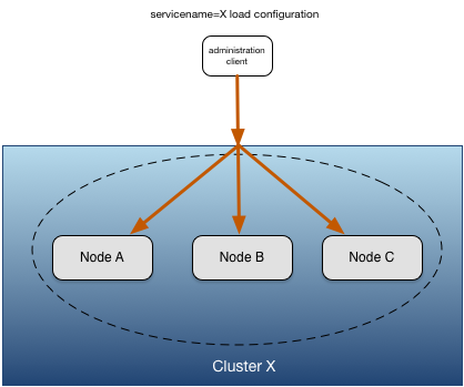
Administrative commands can be sent to multiple nodes in a cluster using a partially qualified service name. When using a
partially qualified service name, the administrative command is sent to all resolved nodes. Figure 5, “Multi-node administration commands” shows a load configuration command being sent to all nodes in cluster X with a single command. A partially qualified service name of X, which is the cluster name, is used so it resolves to all nodes in the cluster.
Nodes being addressed by either the administration network address or a service name can be in the same data center or in a different data center communicating over a WAN.
The most fundamental control that you have over a node is to manage its life cycle. A node can be installed, started, stopped, and removed, as shown in Figure 6, “Node life cycle”.
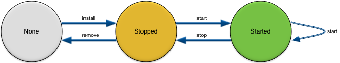
The following sections describe what happens as a node transitions between these states.
To install a node, you use an administration client to perform an install node command. As shown in Figure 7, “Installing a node”, installing a node requires:
-
The StreamBase product to be installed on the machine on which the node is being installed.
-
The application archive for the application being installed.
-
An optional node deploy configuration file.
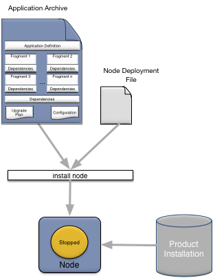
After a node is successfully installed, the following has occurred:
-
Application container services have started.
-
The administration services have started.
-
The application archive has installed into the node directory.
-
The default application configuration and the node deploy configuration have been processed.
-
All application fragment engines have installed.
-
The node is in the Stopped state.
The node can now be started.
Start a node using an administrative client as shown in Figure 8, “Starting a node”.
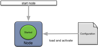
When a node is started these actions occur:
-
Configuration files are loaded and activated.
-
All application fragment engines are started.
-
The node joins the cluster.
-
The node transitions to the Started state.
Starting an already-started node succeeds without taking any action.
Stopping a node is done using an administrative client as shown in Figure 9, “Stopping a node”.
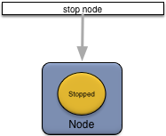
When a node is stopped these actions occur:
-
Configuration files are deactivated and unloaded.
-
All application fragment engines are stopped.
-
The node leaves the cluster.
-
The node transitions to the Stopped state.
Remove a node using an administrative client as shown in Figure 10, “Removing a node”.
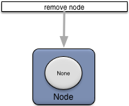
When a node is removed these actions occur:
-
All application container services are stopped.
-
Administration services are stopped.
-
All application fragment engines are removed.
-
The node directory is removed.
One or more engines can run on a node. Each engine hosts a single fragment and has a unique name. In the default case, there is an engine executing for each fragment in an application. However, you can change this in the node deploy configuration so that multiple engines execute the same fragment.
When a node is installed, all engines are also installed. See Install Node for details.
When a node is removed, all engines are also removed. See Remove Node for details.
Figure 11, “Engine life-cycle” shows the engine life cycle, which is affected by both engine and node commands.
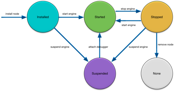
In addition to engines being started when a node is started (see Start Node), engines can also be individually started using an administration command as shown in Figure 12, “Starting an engine”.
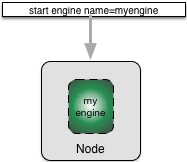
Starting an individual engine does not affect other engines running on a node. You can stop an engine as described in Stop Engine without having to stop the node.
In addition to engines being stopped when a node is stopped (see Stop Node), you can individually stop engines using an administration command as shown in Figure 13, “Stopping an engine”.
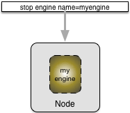
Stopping an individual engine does not affect other engines running on a node. You can restart a stopped engine as described in Start Engine.
You can individually suspend engines instead of restarting them, to facilitate debugging. Engines are individually suspended using the suspend engine command as shown in Figure 14, “Suspending an engine”.
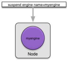
Suspending an individual engine has no impact on any other engines running on a node. You can start a suspended engine by attaching a debugger to the engine.
Suspending an engine has no impact on the state of any configuration.
epadmin provides a command line tool to support all administrative commands and provides a simple mechanism to allow scripting of operational functions.
Many administrative commands are also supported using JMX, and platform log messages are also exposed as JMX notifications. This allows any off-the-shelf JMX console to be used to manage nodes. See JMX Monitoring.