Bridges among Dynamic TCP Meshes
You can use transport bridges to link the disjoint mesh topologies that a dynamic TCP mesh transport establishes in satellite locations.
A dynamic TCP mesh definition establishes a bus with full mesh topology among all its endpoints, as long as their applications connect to a single realm server process. When your enterprise uses satellite realm servers, a single dynamic TCP transport definition establishes a separate mesh for each satellite. Each mesh includes all the applications that are clients of one of the affiliated realm servers. You can use transport bridges to link those otherwise disjoint meshes.
You can define a transport bridge to interconnect dynamic TCP meshes similarly to other bridges.
For more background information, see Dynamic TCP Transport.
Principles of Operation
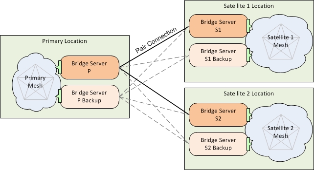
The following diagram depicts the general use case of a dynamic TCP bridge.
This enterprise includes three locations: the primary location (left) and two satellite locations (right). Each location has an affiliated realm server process (not shown). The realm defines a single dynamic TCP transport definition, which establishes a mesh at each location. The meshes are disjoint from one another.
To bridge the meshes requires a bridge server at each location (orange), and a bridge definition that links the locations using a pair of static TCP listen and connect definitions. Include the listen end at the primary location, and the connect end at the satellite locations. The resulting pair connections link each of the satellite bridge servers to the primary bridge server (solid lines).
To extend to a fault-tolerant scenario, add a backup bridge server at each location (light orange). In their bridge definitions, use a second pair of static TCP listen and connect definitions that target the backup bridge server at the primary location. The resulting pair connections link both bridge servers at the each satellite location connect to both bridge servers at the primary location (solid lines and dashed lines).

